


MGE UPS SYSTEMS CleanWave - Installation and user manual Page 10/13
Version 2.1 - 21/04/05 - (JME)
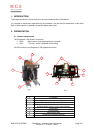
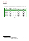
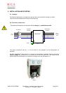
The connections are the following :
Terminal Connection
1 L1 upstream
2 L2 upstream
3 L3 upstream
4N upstream
5 N downstream
6 L1 downstream
7 L2 downstream
8 L3 downstream
Earth Earth (PE)
Table 9
The terminals must be properly tightened according to the size of the bolds.
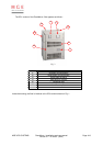
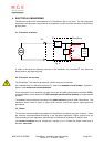
Temperature switches are optionally foreseen on both the Lo and Zo elements for the detection of a
possible over-heating. In that case, for each element, two voltage-free contacts are available :
Terminals Connection
A1 - A2 Normally open contact ‘Warning’ (165°C)
D1 - D2 Normally closed contact ‘Alarm’ (190°C)
Table 10
These contacts are connected on two small terminal boards ( Fig. 2 - "9" ).
They are foreseen for a maximum current of 5A and a maximum voltage of 230V AC.
5.3. E
NERGISING
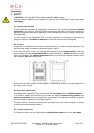
For obvious safety reasons, the energising of the filter can only happen once the housing is
perfectly secured.
During the energising of the filter, the loads downstream the CleanWave
®
filter will also be fed. It is
the technician's responsibility to check that the downstream installation can safely be
energised.
Once the filter energised, the displays on the front side (IP21 version only) should indicate some
upstream and downstream currents.