


MGE UPS SYSTEMS CleanWave - Installation and user manual Page 8/13
Version 2.1 - 21/04/05 - (JME)
4. ELECTRICAL ENGINEERING
The electrical study for the implementation of a CleanWave
filter is very easy. The few instructions
described in this document must however be respected in order to ensure the safety and efficiency
of the system.
4.1. E
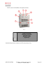
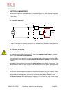
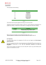
LECTRICAL SCHEMATIC
Z
0
L
0
Non
linear
load
CleanWave
a
D1
Fig. 6
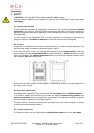
In order to minimise the disturbing currents in the installation, the CleanWave
®
filter should be
placed close to the disturbing load.
4.2. E
LECTRICAL PROTECTIONS
The CleanWave
filter must be protected in a similar way as a transformer.
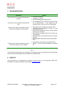
As a standard rule, the electrical protection D1 must be a tetrapolar circuit breaker ( 3 phases +
neutral ) with neutral over-current detection.
If such a protection is not possible (e.g. when the neutral and earth connectors are common (PEN)),
a tripolar breaker will be used and the PEN conductor section will be doubled, as recommended
in table 4.
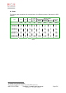
The breakers must be selected according to the phase current as given in table 4 here above. The
maximum inrush current is lower or equal to the nominal current and doesn't require particular
precautions.
4.3. W
IRING
The minimum recommended wiring sections for the different connectors are given in table 4. These
are minimum recommendations according to the European regulations. Higher sections may be
used according to local regulations, particularities of the electrical installation or specific rules.
The neutral conductor may be crossed by a current up to 1.8 times the phase current and is
therefore over-sized.