MGE
TM
Galaxy
TM
6000 : Specification guide
Parallel UPS, three-phase, 250 to 3000 kVA*
* Power rating for an N+1 redundant configuration
APC By Schneider Electric Edition - 03/2009 Spec. E - 12
10 - User interface and communication
10.1 - User interface
UPS operation shall be facilitated by a user interface comprising:
ω a graphic display (at least quarter VGA and high resolution are preferable);
ω controls;
ω status indications with mimic panel.
10.1.1 - Graphic display
The graphic display shall facilitate operation by offering the functions listed below.
ω operating language
It shall be possible to display in the
language all the operating information supplied on the
screens.
ω step by step operating help
The graphic display shall assist the user by providing step by step help in the user's language.
ω animated colour mimic diagram
The mimic diagram shall enable display of installation parameters, configuration, operating status and alarms and
indication of operator instructions for switching operations (e.g. bypass).
ω display of measurements
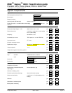
It shall be possible to display the following measurements:
- inverter output phase-to-phase voltages;
- inverter output currents;
- inverter output frequency;
- voltage across battery terminals;
- battery charge or discharge current;
- rectifier/charger input phase-to-phase voltages;
- rectifier/charger input currents;
- crest factor;
- active and apparent power;
- power factor of the load;
- battery temperature.
ω display of status conditions and events
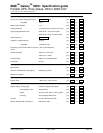
It shall be possible to display the following indications:
- load on battery power;
- load on UPS;
- load on automatic bypass;
- general alarm;
- battery fault;
- remaining battery backup time;
- low battery warning;
- bypass AC source outside tolerances;
-
battery temperature.
Additional information shall be provided in view of accelerating servicing of the system, as specified in section 11
“Maintainability”.
ω display of operating graphs
It shall be possible to display on the screen curves and bargraphs over significant periods for the measurements
mentioned above.
ω log of time-stamped events
This function shall store in memory and make available, for automatic or manually initiated recall, time-stamped
logs of all important status changes, faults and malfunctions, complete with an analysis and display of
troubleshooting procedures. It shall be possible to time stamp and store at least 3 000 events.
10.1.2 - Controls
The UPS shall comprise the following controls:
ω two ON and OFF buttons
Located on the front panel of the UPS, they shall control UPS-unit ON/OFF status.
It shall be possible to turn OFF the UPS externally via an isolated dry contact.
ω EPO terminal block
The UPS shall be equipped with an emergency power off terminal block for complete system shutdown following
reception of an external control signal. The EPO command shall result in:
- shutdown of UPS units;
- opening of the static switch on the bypass line and of the battery circuit breaker;
- opening of an isolated dry contact on the programmable card.
ω alarm reset button
This button shall turn off audio alarms (buzzer) (see section 10.1.3). If a new alarm is detected after clearing the
first, the buzzer sounds again.


