


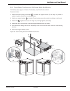
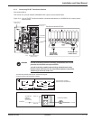
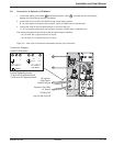
2.7.2 Connecting EX RT Transformer Module
(Part number 86211)
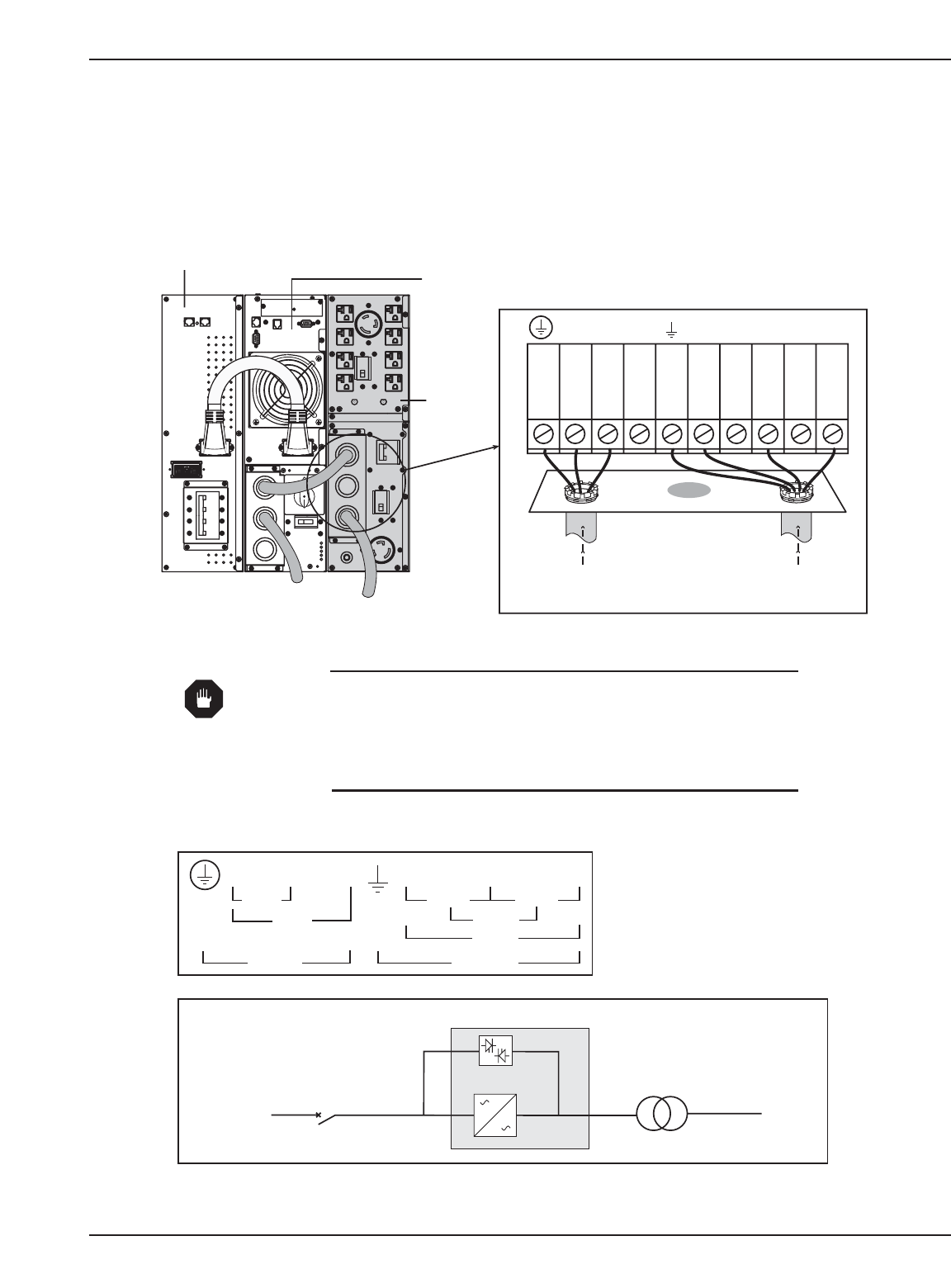
This module is to provide isolated 120/208/240 VAC outputs to the protected loads.
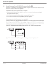
Figure 2-13: View of EX RT Transformer Module connected downstream for 120/208/240 Vac outputs (shown
with one EXB).
Installation and User Manual
Installation 2 — 1586-86000-00 B00
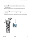
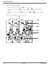
POWER MODULE
EX 5/7/11 RT
TRANSFORMER
MODULE EX RT
AC NORMAL
INPUT
TRANSFORMER MODULE
OUTPUT TO LOAD
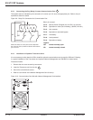
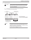
Terminal Block Transformer Module Connection diagram
(located on bottom of Transformer I/O Box)
L3 L2 L1 Lb Ld N Lc La
208Vac
240Vac
AC Input
120Vac
208Vac
AC Output
120Vac
240Vac
Terminal Block capability :
AWG 4 solid or stranded wire.
BATTERY MODULE
EXB 5/7/11 RT
AC INPUT
UPSTREAM
CIRCUIT
BREAKER
(NOT SUPPLIED)
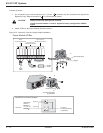
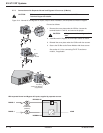
Transformer Module
Bypass AC
Normal AC
Simplified Connection Diagram
To Load
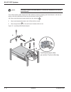
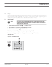
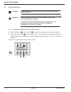
WARNING To avoid overloading transformer windings, provide branch over current
protection for all transformer output terminals.
To avoid overloading 120VAC output windings, distribute loads evenly
between Load 2 and Load 4 (on rear of Transformer Module ) and between
120VAC output terminals (Lb-N, La-N.)
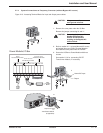
AC Input from
Power Module
(208VAC shown)
AC Output to Load
(120VAC shown)
L3 L2 L1 Lb Ld N Lc La
Transformer Module I/O Box