


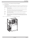
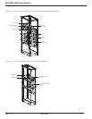
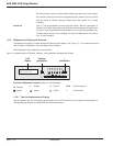
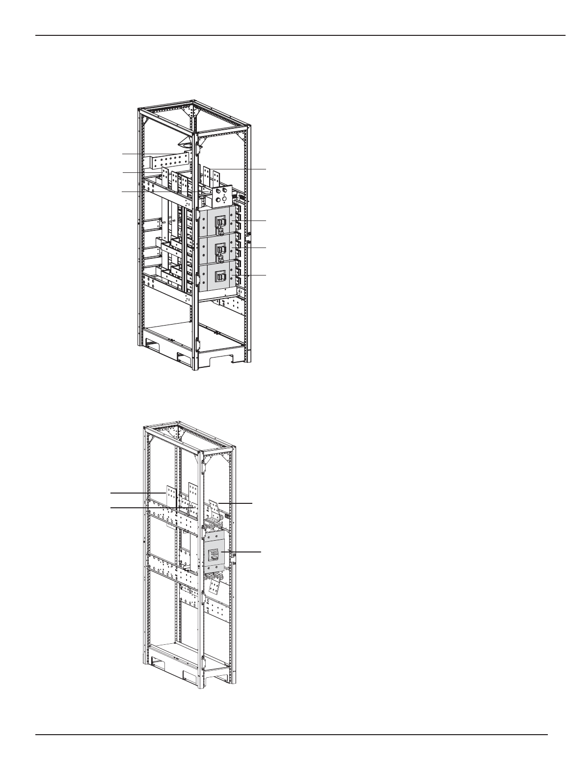
Figure 1-3: Circuit Breaker Locations on the Maintenance Bypass Cabinet.
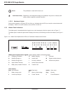
Figure 1-4: Circuit Breaker Locations on the Q4S Cabinet.
Introduction
EPS 8000 UPS Single Module
page 1 — 4
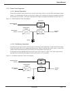
BYPASS INPUT
A, B, C
NEUTRAL
GROUND
BYPASS INPUT CB
Q4S
GROUND
BYPASS INPUT
A, B, C
NEUTRAL
Q5N
OUTPUT
A, B, C
Q3BP
Q4S
(optional)