


Contents
page c iii
Users Manual
Figures
figure description . . . . . . . . . . . . . . . . . . . . . . . . . . . . . . . . . . . . . . . . .page
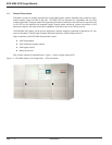
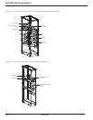
1-1 EPS 8000 System, S-M Configuration, 1 GCC per Module . . . . . . .1-2
1-2 Circuit Breaker Locations on the EPS 8000. (Q4S not shown) . . . .1-3
1-3 Circuit Breaker Locations on the Maintenance Bypass Cabinet . . .1-4
1-4 Circuit Breaker Locations on the Q4S Cabinet. . . . . . . . . . . . . . . .1-4
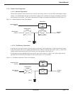
1-5 Normal Operation, Power Flow Diagram . . . . . . . . . . . . . . . . . . . .1-5
1-6 On-Battery Operation, Power Flow Diagram . . . . . . . . . . . . . . . . . .1-5
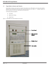
1-7 EPS 8000 Front Panel Indicators and Controls. . . . . . . . . . . . . . . .1-6
1-8 Front Panel Indicators and Control Display . . . . . . . . . . . . . . . . . .1-7
1-9 Alphanumeric Display and Controls . . . . . . . . . . . . . . . . . . . . . . . .1-8
1-10 Hidden Panel Indicator Controls . . . . . . . . . . . . . . . . . . . . . . . . . .1-10
2-1 Default Status Screen Alphanumerical Display Configuration. . . . . .2-1
2-2 Settings Selection Display Screen. . . . . . . . . . . . . . . . . . . . . . . . .2-2
2-3 Sequential Alarm Messages for Viewing the Fault Log . . . . . . . . . .2-3
2-4 Measurement Sensors Located throughout the EPS 8000 S-M UPS2-3
2-5 Voltage Measurement Displays . . . . . . . . . . . . . . . . . . . . . . . . . . .2-4
2-6 Current Measurements Displays . . . . . . . . . . . . . . . . . . . . . . . . . .2-5
2-7 Power and Frequency Measurements Displays . . . . . . . . . . . . . . .2-6
2-8 Battery Measurements Displays . . . . . . . . . . . . . . . . . . . . . . . . . . .2-7