


3400753300/AE - Page 15
2726
25
1817
16
24
20
19
21 22 23 272625
18
1716
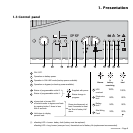
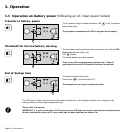
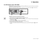
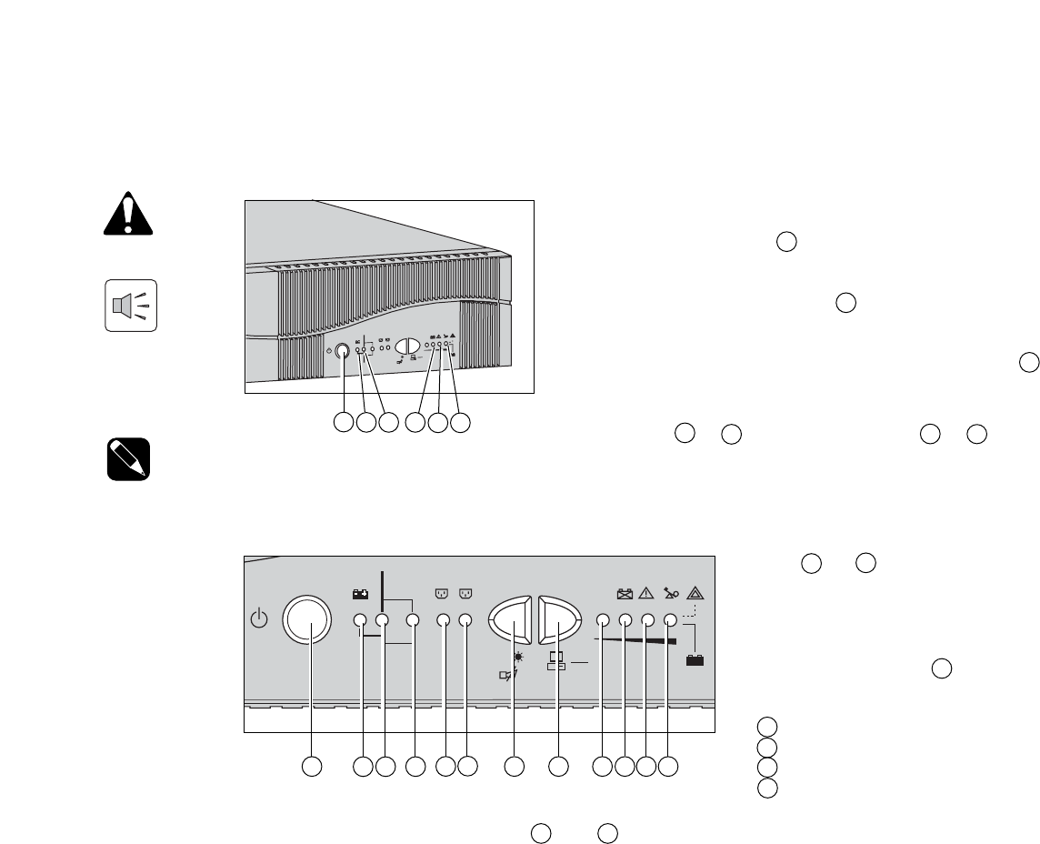
Description of LED indicator status 20 and 21 for programmable outlets 1 and 2:
◗ OFF: the outlets are not supplied with power.
◗ Flashing: status change in progress.
◗ ON: the outlets are supplied with power.
Outlets 1 and 2 can be remotely programmed and controlled.
They may be used for sequential start-up of the protected applications, shedding of non-priority applications during
operation on battery power, and priority management at the end of battery backup time to reserve the longest possible
backup time for the most sensitive applications. These outlets are programmed using Solution Pac software.
LEDs 24 to 27 provide three
different indications:
1. Remaining backup time in percent
(during normal operation).
2. Percent load drawn by the protected
equipment, when button 23 is pressed.
3. Operating faults (flashing LED and
beeps):
27 Overload.
26 UPS fault.
25 Battery fault or end of life warning.
24 Site wiring Fault
3.2 LED indicators
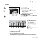
CAUTION:The AC input power source must be present when
energizing for the first time.
1. Press the ON / OFF button 16 .
◗ The buzzer beeps and all the LEDs go ON.
◗ The buzzer beeps twice, then:
◗ If AC input power is available, LED 18 goes ON, indicating
operation in ON-LINE mode.
◗ If AC input power is not available and the UPS is configured for
automatic restart mode, the buzzer beeps three times and LED 17
goes ON, signalling operation on battery power.
All connected equipment is energized.
NOTE: If LEDs 17 or 18 do not turn ON or if LEDs 25 to 27 flash,
there is a fault (see section 4.1).
3.1 Start-up
3. Operation
The protected equipment connected to the UPS can be energized, whether AC input power is available or not.
100%
80%
50%
20%
test
%
1
2
%
BYPASS
1
0
0
%
8
0
%
5
0
%
2
0
%
t
e
s
t
%
1
2
%
B
Y
P
A
S
S