


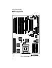
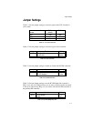
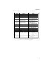
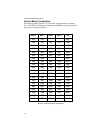

Table 2-12 lists the jumper settings for case and peripheral connections.
Jumper Function Notes
J19 PCI IDE Connector Primary
J20 ISA IDE Connector Secondary
J21 Floppy Connector
J18 Parallel Port Connector Can be disabled at the
CMOS configuration screen.
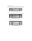
J12 Serial Port (Com1) Can be disabled at the
CMOS configuration screen.
J11 Serial Port (Com 2) Can be disabled at the
CMOS configuration screen.
J9 AT Keyboard AT Version only
J8 & J15 PS/2 Mouse and Keybd. PS/2 Version only
J10 Ext. Keyboard 1- Clock(Keybd), 2-Data,
3-N/C, 4-Ground, 5-VCC
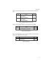
J16 & J17 Power Supply Connector
J34 Hard Disk LED 1-+5V DC, 2-Ground
J35 Reset
J38 Turbo LED 1-+5V DC, 2-Ground
J37 Keylock/Power LED 1-Power; 2-N/C; 3-Ground;
4-Keyboard Lock; 5-Ground
J36 Speaker Connector 1-Speaker; 2-N/C;
3-Ground; 4-5V DC
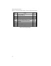
J29 12V Fan Connector 1-+12V DC, 2-Ground
Table 2-12 Case and Peripheral Connections
Jumper Settings
2-7