vii
List of Figures
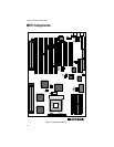
Figure 2-1: M5Pi System Board ...................................................................... 2-2
Figure 3-1: Installing a 72-Pin SIMM.............................................................. 3-5
Figure 3-3: Installing a PCI Peripheral Card .................................................... 3-7
Figure 3-5: Installing an ISA Card .................................................................. 3-8
Figure 4-1: Power-Up Screen .......................................................................... 4-2
Figure 4-2: CMOS Main Screen...................................................................... 4-3
Figure 4-3: CMOS Extended Screen ............................................................... 4-5
Figure 4-4: Exit Pop-up Screen........................................................................ 4-8
List of Tables
Table 2-1: CPU Speed Selection ..................................................................... 2-3
Table 2-2: Video Selection .............................................................................. 2-3
Table 2-3: PCI IDE Selection........................................................................... 2-3
Table 2-4: PCI IDE IRQ14 Selection ................................................................ 2-3
Table 2-5: Secondary IDE Controller IRQ Selection ....................................... 2-4
Table 2-6: IDE DMA Channel Selection ......................................................... 2-4
Table 2-7: Parallel Port IRQ Selection ............................................................. 2-4
Table 2-8: Parallel Port DMA Channel Selection ............................................ 2-5
Table 2-9: Flash ROM Selection ..................................................................... 2-5
Table 2-10: BIOS Reset ................................................................................... 2-5
Table 2-11: Reserved Jumper Settings............................................................ 2-6
Table 2-12: Case and Peripheral Connections ................................................ 2-7
Table 3-1: Common Memory Configurations.................................................. 3-4


