


WEM INSTALLATION & OPERATION (cont’d)
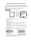
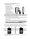
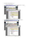
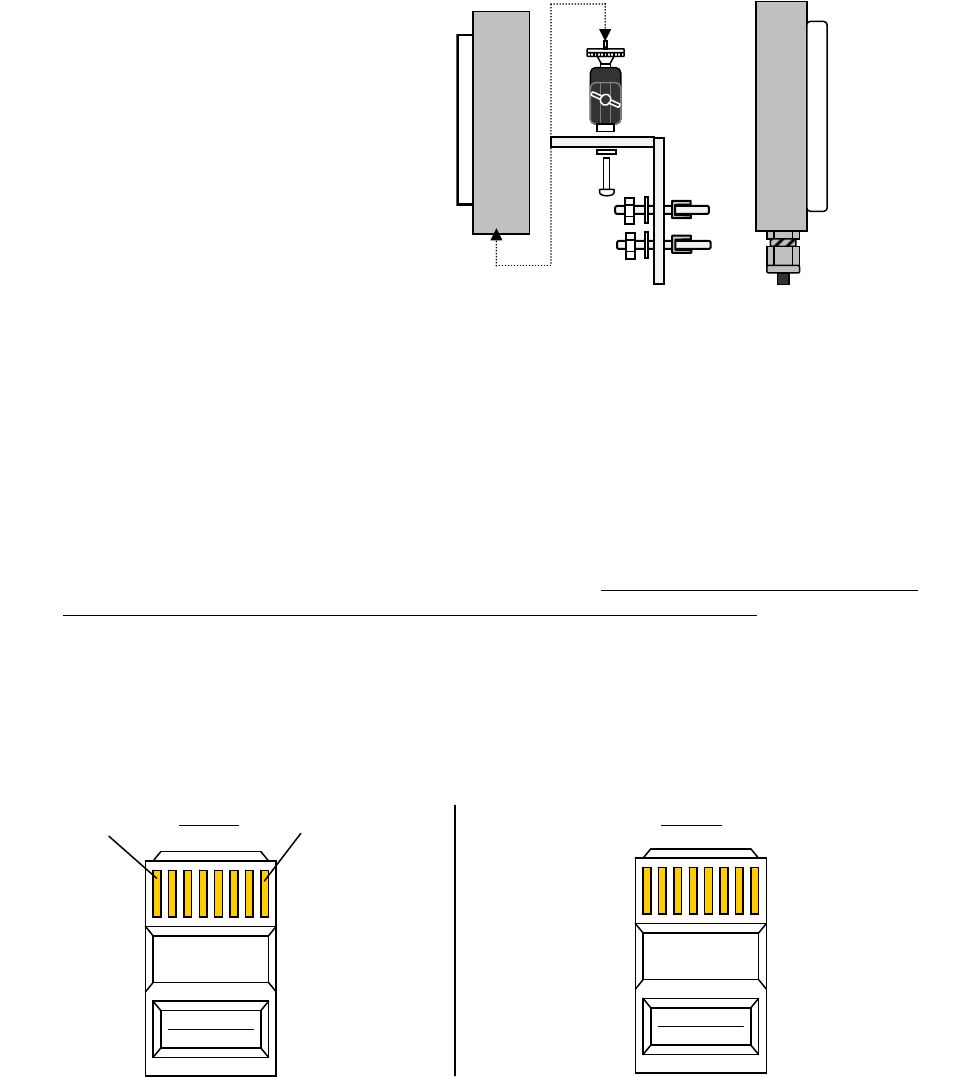
B. MOUNT DIRECTIONAL HOST/CLIENT
Mount the Host/Client with the
included wall/pole mount
bracket and hardware. Connect
the black mounting assembly with
adjustment swivel to mounting
L-shaped bracket with the ¼ - 20 button
head screw. Connect the unit to the
mounting assembly using the ¼-20
mounting hole in the case.
Position the Host and point
it in the direction of the Client (or vice-
versa) and tighten the swivel mount.
Lock in the antenna upon a solid
green Signal Level LED on the Client side.
The Host may flash if it is a multi-connect Host.
Directional WEM
B-1 B-2
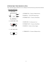
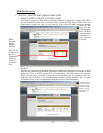
C. MOUNT OMNI-DIRECTIONAL HOST (IF APPLICABLE)
Due to the orientation of the MiniLink Omni-directional Host when mounted, the unit must be
kept inside a weatherproof housing. If the Weather Enclosure was purchased from MicroTek
then it will come with pole/wall mounting hardware and instructions.
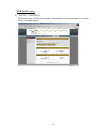
D. CONFIGURE CABLE
Determine the length of CAT5 cable that will be needed and where the PIM will be located. The
total cable length from the radio to the Ethernet device cannot exceed 300 feet, however, the
PIM can be located anywhere along the 300 feet of cable. The PIM and power supply are not
weather proof and must be placed indoors or in an environmental enclosure. On the Host or
Client end, feed the CAT5 cable through the supplied weatherproof connector. Crimp an RJ45
CAT5 connector on the end of the cable and configure as a straight-through patch cable.
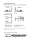
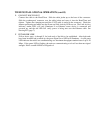
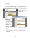
The Ethernet standard straight-through cable configurations used must be configured to one
of the two Ethernet standards (568-A or 568-B) in order for the WES system to operate
correctly. Any deviation from one of the two standard configurations can lead to undesired
activity so make sure your cables are configured as shown in one of the drawings below:
568-A
Green/White 1
Solid Green 2
Orange/White 3
Solid Blue 4
5 Blue/White
6 Solid Orange
- Drawings shown with gold pins facing up and RJ-45 clip in rear (clip not shown)
- If 568-B is configured on end of a CAT5 cable and 568-A is configured on the other end, that configuration
would be a standard crossover cable.
- 7 -
7 Brown/White
8 Solid Brown
568-B
Orange/White 1
Solid Orange 2
Green/White 3
Solid Blue 4
5 Blue/White
6 Solid Green
7 Brown/White
8 Solid Brown
1
8
NOTE: The WEM antenna must be mounted as depicted above (Fig B-1 & B-2) to preserve its weatherproof
capability. The RJ-45 port must be protected by the port plug and positioned underneath to prevent moisture
p
oolin
g
. Ti
g
hten weather
p
roof strain-relief so that it is snu
g
, however, the cable should be able to move.
RJ-45
Connector
RJ-45
Connector