24
P
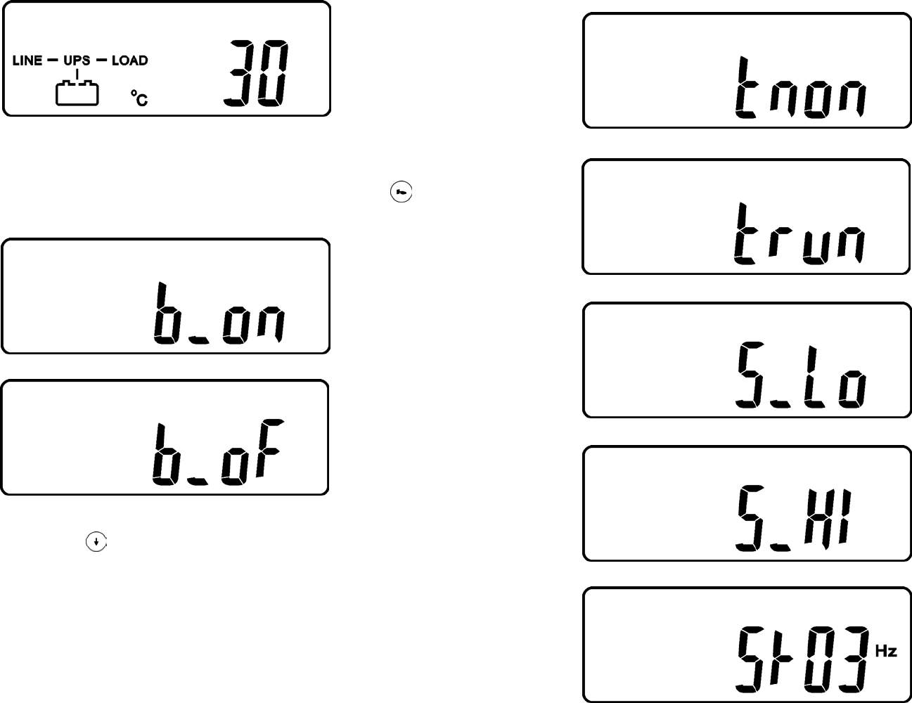
* It shows the Internal Temperature of the UPS System.
3.6.4 UPS Default Data and Special Function Features
3.6.4.1 Once the UPS has successfully started up, press the Special Function
keypad to change the LCD display screen to drawing Q1.
Q1
* It shows the Buzzer is “Enabled”.
Q2
* It shows the Buzzer is “Disabled”.
3.6.4.2 Press the scroll down
keypad to check the UPS settings.
Drawing Q1 (Buzzer/audible alarm)
Drawing R1 (Self-test)
Drawing S1 (Bypass Voltage Window)
Drawing T (Output Frequency Synchronization Window)
Drawing U (Inverter Output Voltage)
Drawing V1 (UPS Operation Mode)
Drawing W (Output Voltage Fine Tune)
Drawing X (UPS ID)
Drawing Y (Number of UPSs in Parallel)
25
R1
* It shows the Self-test is “Disabled”.
R2
* It shows the Self-test is “Enabled”.
S1
* It shows the Bypass Voltage is adjusted to the lower limit.
S2
* It shows the bypass voltage is adjusted to the higher limit.
T
* It shows the Frequency Window is +/-3Hz.


