


39
Analog I/O function
1
PLC FUNCTION
1.10 Analog I/O function
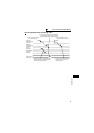
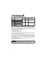
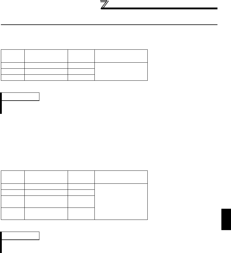
1.10.1 Analog input
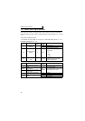
Analog input value of termianl 1, 2, 4 can be read from D9245 to D9247.
Actual read processing is performed at the END processing of the sequence.
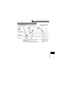
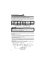
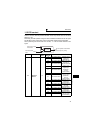
1.10.2 Analog output
Analog output from each terminal can be performed by setting value on D9251 to
D9254.
Output from PLC function can be performed by setting "7" in output signal selection
parameters of each terminal (terminal FM: Pr. 54, terminal AM: Pr. 158, terminal AMO,
AM1: Pr. 306, Pr. 310).
Actual read processing is performed at the END processing of the sequence.
Device
No.
Terminal Name
Setting
Unit
Data Access Enable
Condition
D9245 Terminal 1 input 0.1%
AlwaysD9246 Terminal 2 input 0.1%
D9247 Terminal 4 input 0.1%
REMARKS
Full-scale value of analog input is determined by the setting of Pr. 73 Analog input selection, Pr.
267 Terminal 4 input selection. Refer to the inverter instruction manual (applied).
Device
No.
Terminal Name
Setting
Unit
Data Access Enable
Condition
D9251 Terminal FM 0.1%
Always
D9252 Terminal AM 0.1%
D9253
Terminal AM0
(FR-A7AY)
0.1%
D9254
Terminal AM1
(FR-A7AY)
0.1%
REMARKS
High speed pulse train output (Pr. 291) from terminal FM can be performed. (Refer to the
inverter instruction manual (applied).)