


2
Function Block Diagram
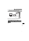
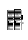
1.1 Function Block Diagram
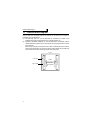
How I/O data are transferred to/from the inverter by the built-in PLC function is
explained using function blocks.
(1) I/O data read, write, etc. can be performed by accessing the inverter in the
predetermined method using special relays, special registers, etc.
(2) Operation, parameter read/write, etc. can be performed in accordance with the
created sequence programs (built in the inverter) using input data from the control
input terminals.
With the output signals, output data can be output to outside the inverter from the
control output terminals as not only the inverter's status signals but also pilot lamp
on/off, interlock and other control signals set freely by the user.
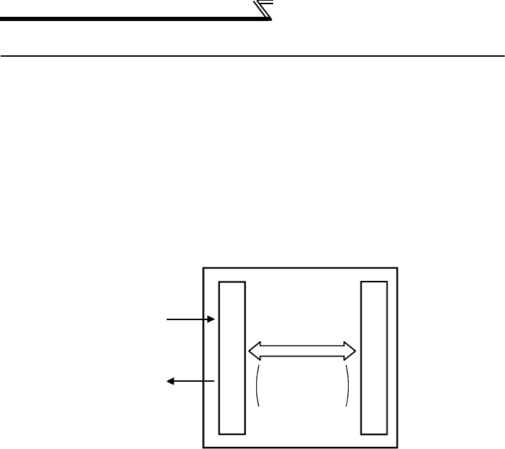
Input signal
Inverter
Output signal
I/O data
Special relays,
special registers,
etc.
Built-in sequence program
Inverter CPU