


55
CC-Link I/O Specifications
2
CC-Link COMMUNICATION
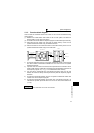
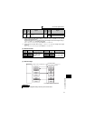
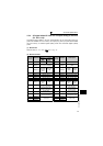
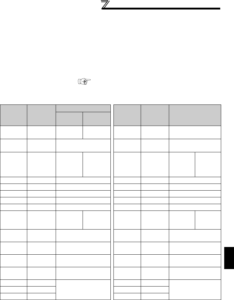
2.3.4 I/O signal when CC-Link Ver.2 octuple setting is selected
(Pr. 544 = 118)
The device points usable in CC-Link communication are 32 input (RX) points (12
points are available for PLC function), 32 output (RY) points (12 points are available
for PLC function), 16 remote register (RWr) points and 16 remote register (RWw)
points.
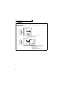
(1) Remote I/O
Same as when Pr. 544 = 112 ( Refer to page 52)
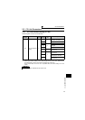
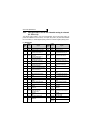
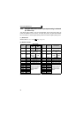
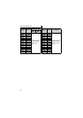
(2) Remote resister
PLC function
device No.
Address
Description
PLC function
device No.
Address Description
Upper 8
Bits
Lower 8
Bits
RWwn
Monitor
code 2
Monitor
code 1
RWrn First monitor value
RWwn+1
Set frequency
(0.01Hz increments)
RWrn+1
Second monitor
value
RWwn+2
Link
parameter
expansion
setting
Instruction
code
RWrn+2
Reply
code2
Reply
code1
RWwn+3 Write data
RWrn+3 Read data
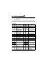
RWwn+4
Monitor code 3
RWrn+4
Third monitor value
RWwn+5
Monitor code 4
RWrn+5
Fourth monitor value
RWwn+6
Monitor code 5
RWrn+6
Fifth monitor value
RWwn+7
Monitor code 6
RWrn+7
Sixth monitor value
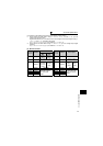
RWwn+8
Alarm
definition
No.
H00 RWrn+8
Alarm
definition
No.
Alarm
definition
data
RWwn+9
PID set point
(0.01% increments) *1
RWrn+9
Alarm definition
(output frequency)
RWwn+A
PID measured value
(0.01% increments) *1
RWrn+A
Alarm definition
(output current)
RWwn+B
PID deviation
(0.01% increments) *1
RWrn+B
Alarm definition
(output voltage)
RWwn+C
toruqe command / limit
(0.01% increments)
RWrn+C
Alarm definition
(energization time)
RWwn+D
H00 (Free)
RWrn+D
H00 (Free) RWwn+E RWrn+E
RWwn+F
RWrn+F
*1 When Pr. 128 = "50, 51, 60, 61", they are valid.