


46
System Configuration
2.1 System Configuration
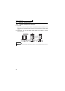
2.1.1 System configuration example
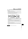
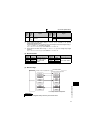
(1) PLC side
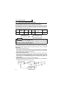
Mount the "Control & Communication Link system master/local module" on the
main base unit or extension base unit of the PLC CPU that will act as the master
station.
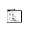
(2) Connect the PLC CC-Link module master station and inverters by CC-Link
dedicated cables.
REMARKS
Refer to the FR-A7NC indtruction manual for the CC-Link communication wiring and CC-Link
cables.
CPU
AJ61
BT11
Master station
Power supply
module
Terminating
resistor
CC-Link dedicated cable
Inverter
Inverter
Up to 42 inverters
can be connected
when only inverters
are connected.
Power supply
Motor Motor
Power
supply