


29
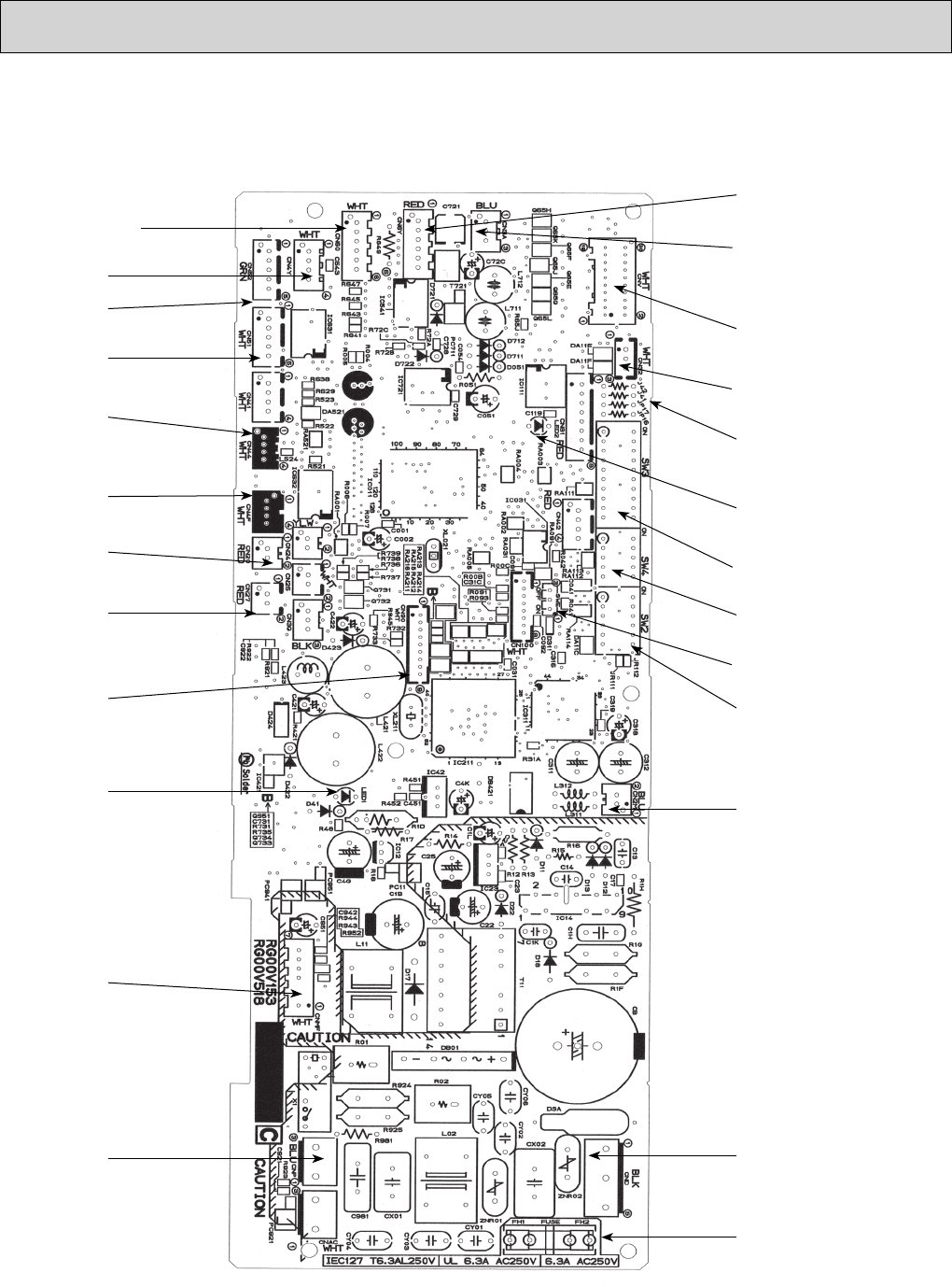
10-3. TEST POINT DIAGRAM
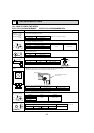
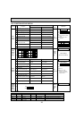
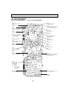
10-3-1. Indoor controller board
PLFY-P12/15/18/24/30/36NBMU-E PLFY-P12/15/18/24/30/36NBMU-ER1
CN52
Remote indicator
CN51
Centrally controlled
CN4Y
i-See sensor
CN2M
Connect to the terminal block (TB5)
(M-NET transmission connecting wire)
24-30VDC (non-polar)
CN3A
Connect to the terminal block (TB15)
(MA-Remote controller connecting wire)
1 - 3 : 8.7-13V DC (Pin1 (+))
LED2
Power supply for
MA-Remote controller
CN32
Remote switch
SW4
Model selection
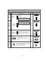
CN60
Linear expansion valve (LEV)
output
12VDC pulse output
SW3
Function setting
SW2
Capacity setting
CN6Y
i-see sensor motor output
12VDC pulse output
CN44
Pipe temperature thermistor
1-2 : Liquid (TH22)
3-4 : Gas (TH23)
CN4F
Drain float switch (FS)
CN20
Room temperature
thermistor (TH21)
CN27
Damper signal output
12VDC(1 : +)
CN90
Connect to the wireless
remote controller board
(W.B)
LED1
Main power supply
(Indoor unit : 208-230V)
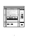
CNMF
Connect to the
fan motor (MF)
1-4 : DC310~340V
5-4 : DC15V
6-4 : DC0~6V
7-4 :
DC0 or DC15V (Stop)
DC7.5V (Operation)
(12VDC pulse)
CNP
Drain pump output (DP)
1-3 : 208-230VAC
FUSE
6.3A 250V
SWE
Test run(Drain pump)
Jumper wire J41, J42
Pair No.setting for wireless
remote controller
CND
Power supply for indoor controller board
3 - 5 : 208-230VAC
CNV
Vane motor output
12VDC pulse