


DX-VS1UE User
DX-VS1UE UserDX-VS1UE User
DX-VS1UE User’
’’
’s Manual
s Manuals Manual
s Manual
7
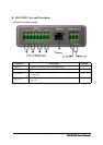
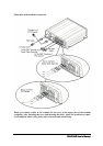
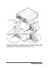
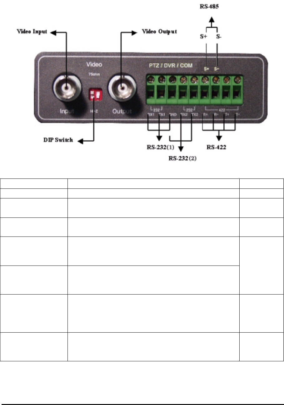
2) Rear View and Description
connector name description remarks
Video Input Connector for inputting video signal using BNC cable
DIP Switch
Switch for designating terminal of video signal of
video input BNC connector(Only left swith is used)
Refer to 4)
Video Output
Connector For outputting video signal using BNC ca-
ble
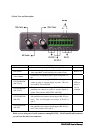
PTZ/DVR/COM
(RS-232(1))
Connector for connecting DX-VS1UE with digital re-
corder in order to operate digital recorder. This con-
sists of RX1,TX1 and GND.
PTZ/DVR/COM
(RS-232(2))
Connector for connecting DX-VS1UE with
pan/tilt/zoom cameras in order to operate digital re-
corder. This consists of RX2,TX2 and GND.
GND ter-
minal is
used in
common
PTZ/DVR/COM
(RS-422)
Connector for communication between DX-VS1UE
and pan/tilt/zoom cameras which support RS-422 pro-
tocol. This is half duplex and consits of R+,R-,T+
and T-.
PTZ/DVR/COM
(RS-485)
Connector for communication between DX-VS1UE
and pan/tilt/zoom cameras which support RS-485 pro-
tocol. This consists of S+ and S-.
While you are using one of serial connecters among RS-232(2) , RS-422 and RS-485 connector,
you can’t use the other two connectors.