


Introduction
10
870 USE 103 00 May 2001
Status Indicators
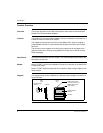
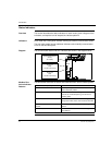
Overview This section describes the status indicators for each model, gives a diagram of the
indicators, and explains how to interpret the indicator patterns.
Indicators Each model has a front panel indicator showing its network communication status.
The dual-cable model has two additional indicators which identify communication
errors on the two cable paths.
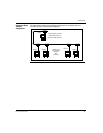
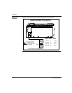
Diagram The communication status and error indicators are shown in the diagram below
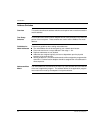
Modbus Plus
Active Indicator
Patterns
The table below describes the status associated with each active indicator pattern.
MB+
ACT
0
1
2
3
4
5
6
7
8
9
0
1
2
3
4
5
6
7
8
9
ERROR
Modbus Plus
Communication Active
(Green)
(All models)
B
Communication Error
Channel A
(Red)
(170 PNT 160 20 only)
Communication Error
Channel B
(Red)
(170 PNT 160 20 only)
A
Indicator Pattern (Green) Status
Six flashes/second Normal operating state. All nodes on a healthy
network flash this pattern.
One flash/second The node is off-line. After being in this state for 5
seconds, the node attempts to go to its normal
operating state.
Two flashes, then OFF for 2 seconds The node detects the network token being passed
among other nodes, but it never receives the token.
Three flashes, then OFF for 1.7
seconds
The node does not detect any token passing on the
network.
Four flashes, then OFF for 1.4 seconds The node has detected another node using the
same address.