


Introduction
14
870 USE 103 00 May 2001
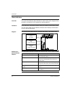
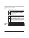
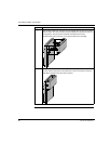
Setting the
Switches
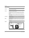
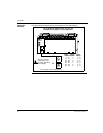
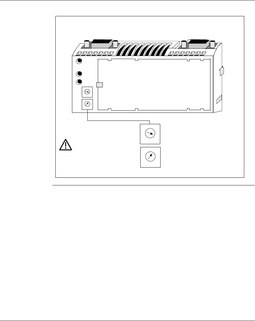
The figure below illustrates how to set a Modbus Plus Node Address.
Do not install any adapter unless you have set
its Modbus PLus address for your application.
1
3
0
9
2
6
4
5
8
7
1
3
0
9
2
6
4
5
8
7
1
3
0
9
2
6
4
5
8
7
1
3
0
9
2
6
4
5
8
7
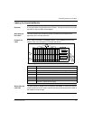
See your network
administator to get
the node address for
each adapter.
This example sets the address to 31.
ERROR
A
B
X10
X1
MB+
ACT
Node
Address
Upper
Switch
Lower
Switch
1... 9
10... 19
20... 29
30... 39
40... 49
50... 59
60... 64
0
1
2
3
4
5
6
1... 9
0... 9
0... 9
0... 9
0... 9
0... 9
0... 4
X10
X1