


Introduction
12
870 USE 103 00 May 2001
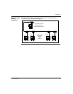
Address Switches
Overview This section describes the address switches and explains how to use them to set the
module address.
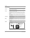
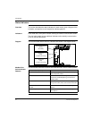
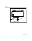
Two Rotary
Switches
Each Modbus Plus Communication Adapter has two rotary switches on the lower left
portion of the front panel. These switches are used to set the Modbus Plus node
address.
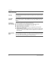
Guidelines for
Node Addresses
Follow these guidelines when setting node addresses:
The node address should be assigned by your network administrator.
Each node must have a unique address in the range 1... 64.
Duplicate addresses are not allowed.
Addresses are assigned logically and are not dependent upon the physical
locations of the node devices.
Starting at address 1, the lowest addresses should be assigned to programmable
controllers. Communication adapters should be assigned the next addresses in
direct sequence.
Addresses Must
Match
The node address is also defined in the Peer Cop Table and MSTR function blocks
of the user’s application program. The address defined in the application program
must match the one set by the adapter's front panel switches.