


Communication Access Registers
42
870 USE 103 00 May 2001
ASCII Header
Block Function
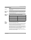
These registers contain an ASCII text description of the module.
ASCII Header
Block
Parameters
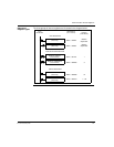
The block length depends upon the type of I/O base to which the adapter is
connected. The maximum length is 64 bytes of ASCII characters, corresponding to
a length of 8...32 words as specified in word 6 of the module status block (at
reference 4F806).
The registers can be read, but cannot be written into.
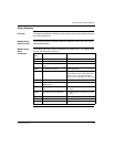
The following table shows the header block layout as a string of ASCII characters as
they are positioned from the starting reference 4FC01.
4FC01+Byte
Offset
ASCIICharacters
Meaning
0...10 MODBUS PLUS Modbus Plus network device
11 20 hex (32 decimal) space
12 20 hex (32 decimal) space
13 14 15 IEC IEC data mode (Data bit order per IEC standard)
16 20 hex (32 decimal) space
17 18 19 DIGEXPANA Digital module (ID range: XX00...XX7F hex)Expert
module (ID range: XX80...XXBF hex)Analog module
(ID range: XXC0...XXFE hex)
20 21 HHLL Module ID code(HH = high byte, LL = low byte)
22 23 I I OO Module I/O words(I I = input words, OO = output
words)
24...63 -- Reserved