


8
Momentum mo8me Manual
6
1
2
3
4
7
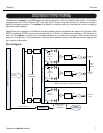
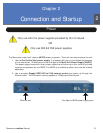
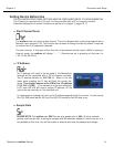
The mo8me enclosure can be used in a number of different confi gurations depending on the needs
of the end user. Units are shipped with rack ears, which can be front or rear mounted or can rotate
for vertical or horizontal surface mounting. Optional rubber stage boots allow the units to be used as
stage boxes.
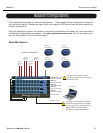
An optional contractor panel can be ordered, which then allows the end user to terminate all analog
connections with simple “phoenix” screw terminal connectors or utilize a standard DB25 “break out
cable” instead of the front panel XLR connectors. This also allows passive “splitting” of the analog
signals if needed. Pro Co offers whatever breakout cables you need. Just ask for them when you
order your system.
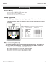
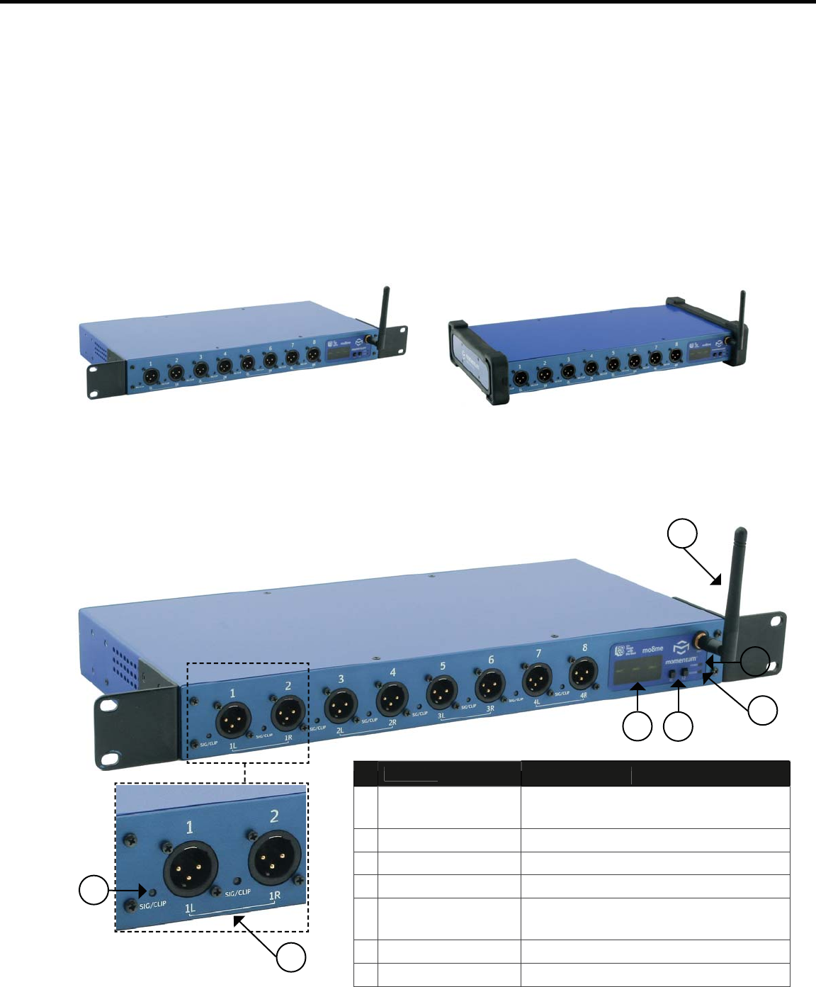
mo8me Front View with optional Stage Boots
mo8me Front View with Rack Ears
Overview
Chapter 1
The mo8me Enclosure
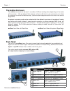
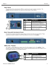
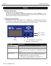
Front Panel
The front of the mo8me has a 2-key control panel, eight channels capable of any combination of
eight mono and four stereo output mixes and an antenna for remote mixing. Each channel has one
signal / clip LED indicator that is visible on the front panel.
The control panel includes a power LED, status LED,
a 3-digit readout display and control keys.
Index
I
n
d
e
x
Description
D
e
s
c
r
i
p
t
i
o
n
1
S
i
g
nal/Clip LE
D
Green = -40dB F.S. or above;
Re
d
= -
3d
B F.S.
o
r
abo
ve
2
S
tere
o
Ch
a
nnel mo8me
o
ffers 4 stere
o
ch
a
nnel
s
3
D
is
pl
a
y
Th
ree c
h
aracter LCD
d
is
pl
a
y
4
F
1
&
F1 Select
o
r
s
S
elect
a
n
d
e
d
it mo8me f
u
ncti
o
ns
5
S
t
a
t
u
s LE
D
Green = Au
d
io s
y
nc
p
resent;
Red = Network faul
t
6
Po
wer LE
D
Green = Di
g
ital power OK
7
A
ntenn
a
C
o
mm
u
nic
a
tes with
m
r
c
5