


— 7 —
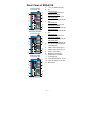
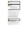
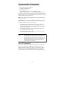
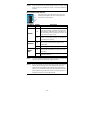
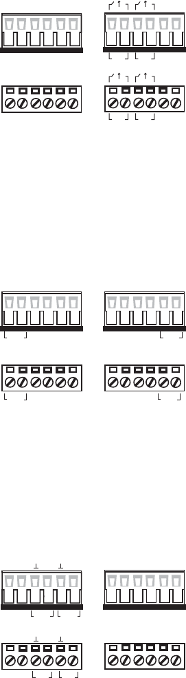
RELAY1
RELAY1
RELAY2
RELAY2
FAULT:
The two sets of relay contacts of the
6-pin terminal block connector are
used to detect user-configured
events. The two wires attached to
the fault contacts form an open
circuit when a user-configured
event is triggered. If a
user-configured event does not
occur, the fault circuit remains
closed.
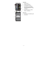
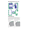
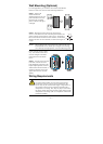
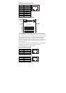
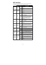
Wiring the Redundant Power Inputs
The EDS-510A has two sets of power inputs—power input 1 and power input
2. The top two contacts and the bottom two contacts of the 6-pin terminal
block connector on the EDS-510A’s top panel are used for the two digital
inputs. The top and front views of one of the terminal block connectors are
shown here.
PWR1
PWR2
V1- V1+
PWR1
V2- V2+
PWR2
V1- V1+V2- V2+
STEP 1: Insert the
negative/positive DC wires into the
V-/V+ terminals, respectively.
STEP 2: To keep the DC wires
from pulling loose, use a small
flat-blade screwdriver to tighten the
wire-clamp screws on the front of
the terminal block connector.
STEP 3: Insert the plastic terminal
block connector prongs into the
terminal block receptor, which is
located on the EDS-510A’s top
panel.
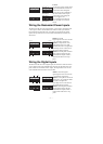
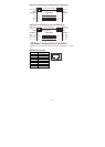
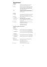
Wiring the Digital Inputs
The EDS-510A has two sets of digital inputs, DI 1 and DI 2. Each DI consists
of two contacts of the 6-pin terminal block connector on the EDS-510A’s top
panel, which are used for the two DC inputs. The top and front views of one
of the terminal block connectors are shown here.
I1
D2I
I2
D1I
I1 I2
D2ID1I
STEP 1: Insert the negative
(ground)/positive DI wires into the
┴/I1 terminals, respectively.
STEP 2: To keep the DI wires from
pulling loose, use a small flat-blade
screwdriver to tighten the
wire-clamp screws on the front of
the terminal block connector.
STEP 3: Insert the plastic terminal
block connector prongs into the
terminal block receptor, which is
located on the EDS-510A’s top
panel.