451-0308 MRV Communications, Inc. www.mrv.com 21
Installing the LX-4000 Series
Connect a category 3 (CAT 3) cable for 10 Mbps operation, or a category 5 (CAT 5) cable for 10/100
Mbps operation to the 10/100 connector on the rear of the LX-4000 Series (see Figure 5) and the other
end to your network. The LINK LED comes on steady green if the cable is properly connected.
Connect Serial Device Cables
Connect the serial device cables to the 8-pin RJ-45 jacks on the rear of the unit.
NOTE: LX-4000 Series serial ports provide concurrent support for RTS/CTS flow control and
modem control. Refer to Appendix A and Appendix D for further information.
Connecting Your Management Station
Connect the management station to the DIAG port (port 0) using the connector and cable you received
with the LX-4000 unit. Refer to “Connecting to the Diagnostic Port (Port 0)” in Appendix D for more
information on DIAG port connections.
Connecting DC Power
This section describes how to connect power to the DC version of the LX Series 4008, 4016, and 4032.
The LX-4048 model is made in an AC version only.
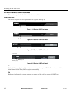
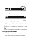
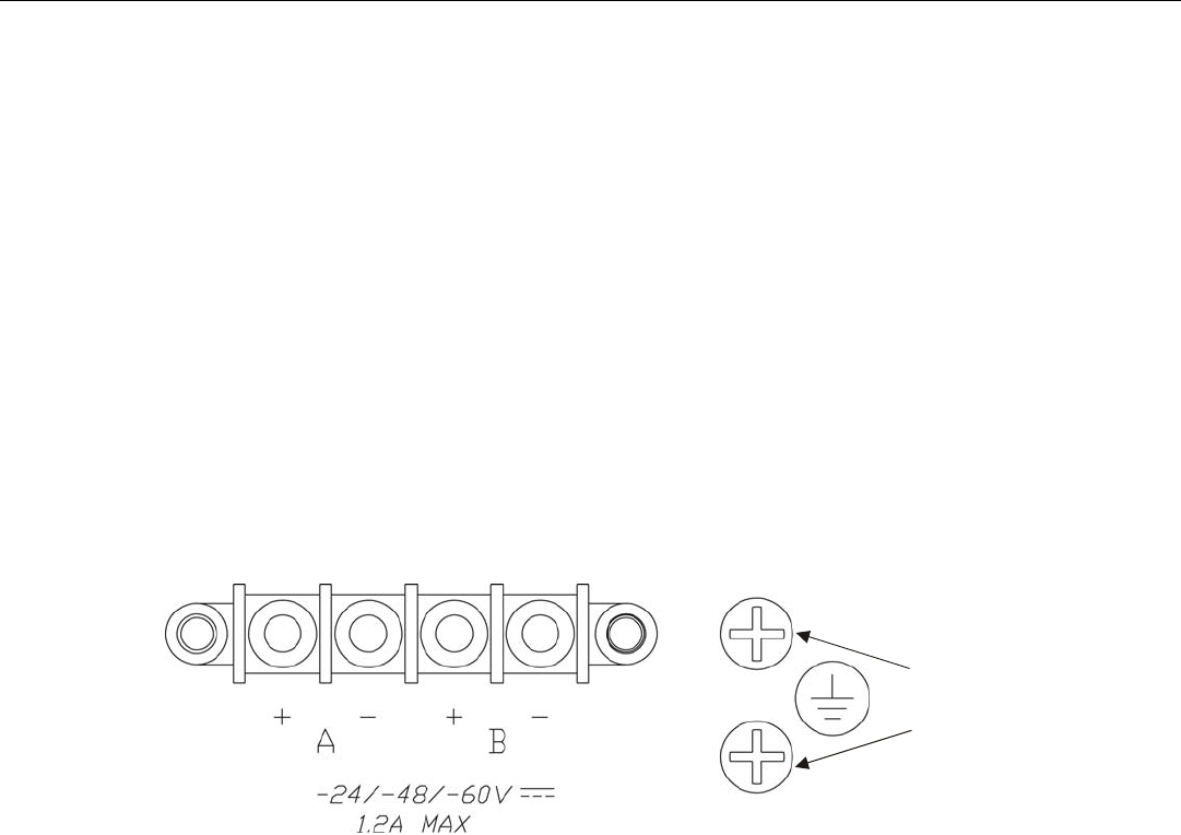
Figure 13 - Connecting DC Power
After you have installed the LX-4000 unit, you can connect the DC power as described in the following
procedure (refer to Figure 13):
1. Connect the LX-4000 to the facility's bonding network (or earth ground), using the points on the
rear panel of the LX-4000. The connection to the facility's bonding network should be made per
local practices, using wire with a minimum conductor size of 18 AWG.
2. Using a ¼-inch nut driver, remove the terminal block nuts.
3. Attach the facility’s “A” feed to the terminal block labeled “A”.
NOTE: Be sure that the -48VDC is connected to the minus side, and the 48VDC return is connected
to the plus side.
4. Attach the facility’s “B” feed to the terminal block labeled “B”.
5. Replace the nuts and tighten them securely.
#10
Grounding
Lugs


