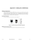
Appendix D - Cabling the LX-4000 Series
58
MRV Communications, Inc. www.mrv.com 451-0308
Ordering and Installing the Inlet Connector Lock
NOTE: The Inlet Connector Lock is available only on the LX-4008, LX-4016, and LX-4032. It is not
supported on the LX-4048.
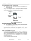
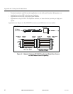
You can use an inlet connector lock to lock the AC power cord to the LX-4000 Series unit. MRV does
not supply this lock. You can order the connector lock (part number 85910020) from Panel
Components Corporation. The web address at which you can order the connector lock is:
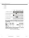
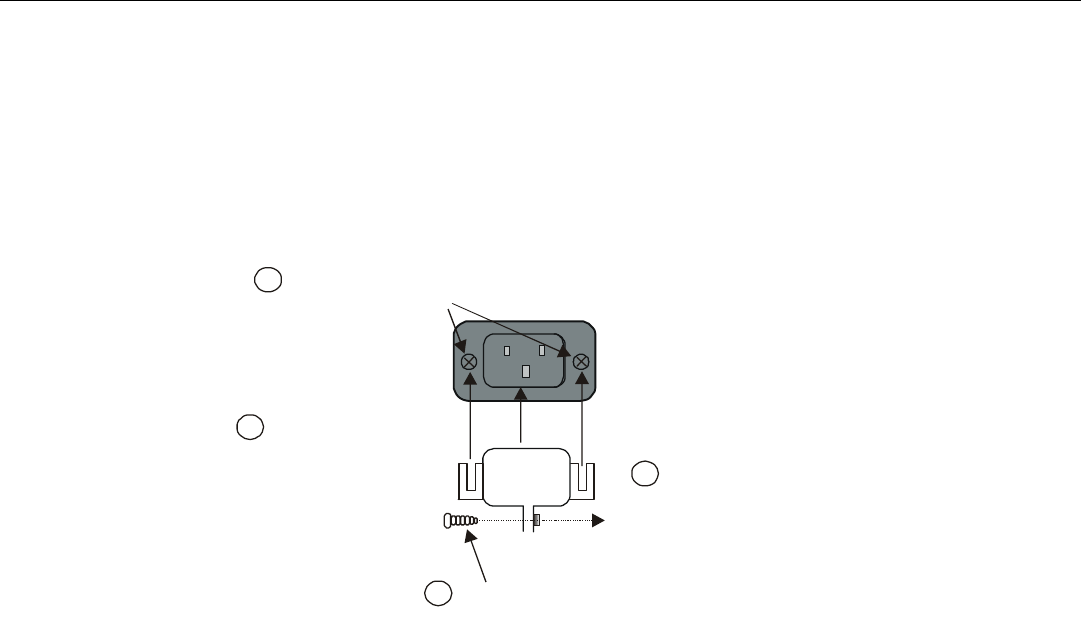
www.panelcomponents.com/first.html. See Figure 26 for installation instructions.
Figure 26 - Installing the Inlet Connector Lock
Connecting to the Diagnostic Port (Port 0)
NOTE: Display problems may occur during bootup when you attach a VT420 terminal to the DIAG
port (port 0) and the VT420 display setup is configured to Smooth-2 Scroll. To avoid this,
change the VT420 scroll setting to Jump Scroll.
Connect the provided serial port cable to the DIAG connector (port 0), and the other end to your
terminal. You can use this direct connect serial link to send commands to the boot loader and
diagnostics. This port is used to log system messages during bootup. You can also use port 0 to
manage and configure the LX-4000 once the unit completes the bootstrap process.
Modem Control/Hardware Flow Control
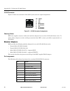
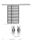
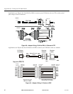
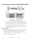
LX-4000 Series serial ports can be set up to support RTS/CTS flow control. The adapters shown in
Figure 27 and Figure 28 illustrate RTS/CTS flow control for DTE devices using DB25 and DB9
connectors. Figure 29 illustrates RTS/CTS flow control for a DB-25 connector on a DCE device like a
modem. LX-4000 Series serial ports can also be set up to support modem control (except for the DIAG
port (port 0)). Figure 27, Figure 28, and Figure 29 support modem control as needed. Only Figure 28
and Figure 29 support concurrent modem control and RTS/CTS flow control between the LX-4000
Serial Port and the attached device.
The adapter shown in Figure 29 supports modem control.
90-250VAC
1.0A 50/60Hz
Insert two 4-40 x
1/4” Philips screws
here. Do not
tighten.
1
Slide the connector
lock ears under the
screw heads.
Tighten the screws.
2
Plug in the power cord
(not shown).
3
Tighten the screw
beneath the connector
lock.
4


