MRV Communications, Inc. – Installation Manual
21
Loop and Remote Loop Operation Mode
Loop
In this state, the device performs a loop on the twisted pair through the Line
Interface, as well as another loop from AIR RX to AIR TX.
Local Loop back
The device on the side of the technician is in LOOP state when dipswitch “1”
is “ON” and Dipswitch “2” is “OFF” (for 4 E1: Dipswitch 3 ON & 4 OFF).
Remote Loop
The device on the opposite side turns to loop state by being controlled from
the near device (Master) – dipswitch “2” in “ON” and dipswitch “1” is “OFF”
(for 4E1: Dipswitch 4 ON and Dipswitch 3 OFF).
In the opposite device (Slave), both dipswitches – 1 and 2 – should be “OFF”
(Normal)(for 4E1 Dipswitches 3&4 OFF).
When turning off the Master, the Slave exits Loop state.
When the Slave does not receive an optical signal for the duration of 0.8
seconds, it exits Loop state. In this situation, when electronic Reset was not
performed on Master, the technician should shut off the device and reactivate
it.
Heating
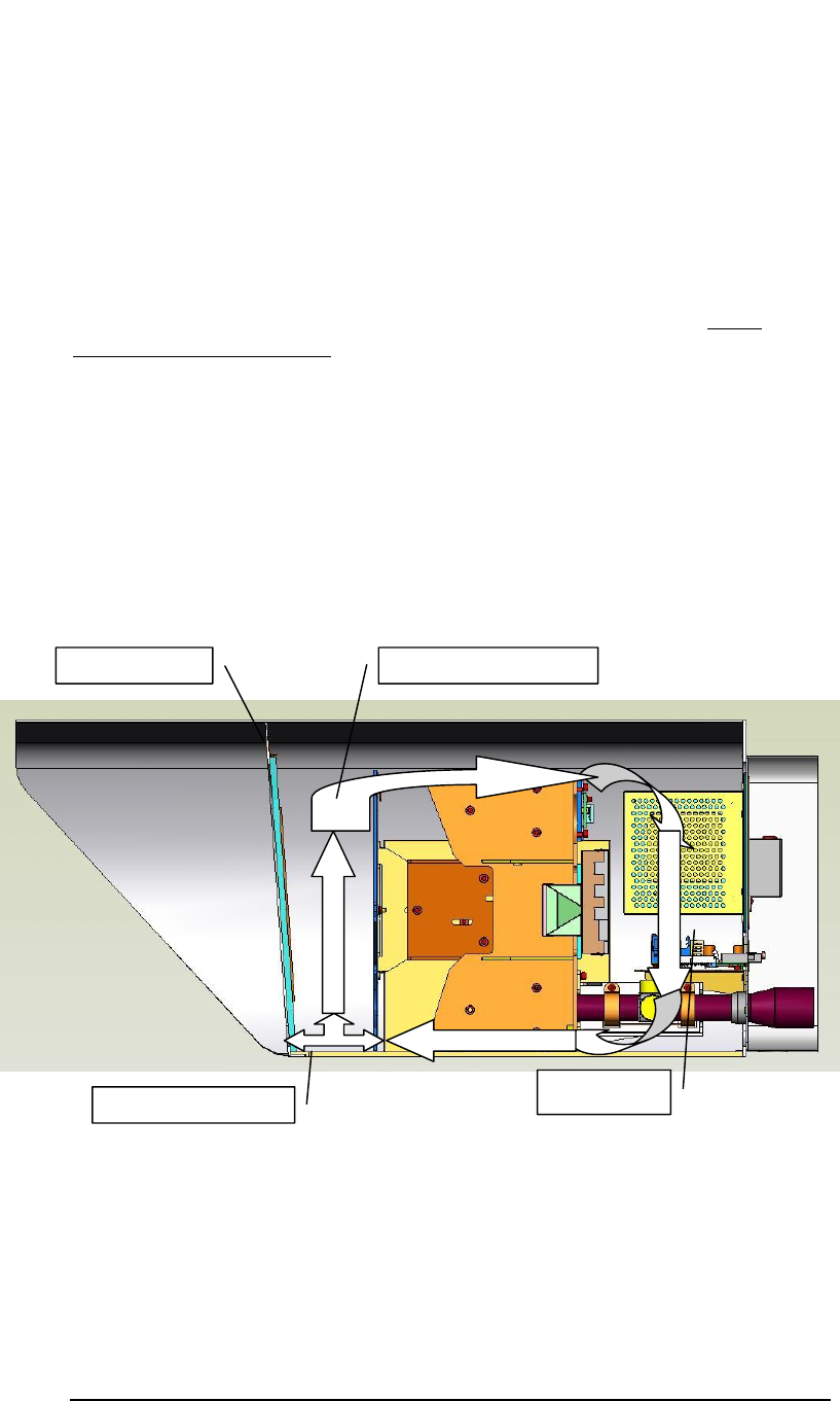
All our TereScope systems are designed with our special internal air circulation
feature, based on dissipation of the power supply heat. This prevents the
formation of condensation on the lenses under all weather conditions without
the need for additional heating at low temperatures
Figure 1.10: Illustration of the air circulation in the TS4000 and TS5000 products
In spite of the aforesaid, an optional front window with the heating system
can be ordered separately (p/n TSX000-HEAT for a link). We recommend
this solution only for extremely adverse weather conditions such as heavy
snow with strong wind or high humidity.
The dissipated heat of about 25W creates a differential of about 10
o
between
the glass and the environment. The Heating is controlled by a Switching and
control circuit
Holes for ventilation
Exam
p
le for air circuit.
Heating are
a
Front window


