


Chapter 2 - Installation & Connection
11
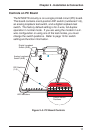
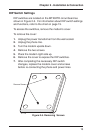
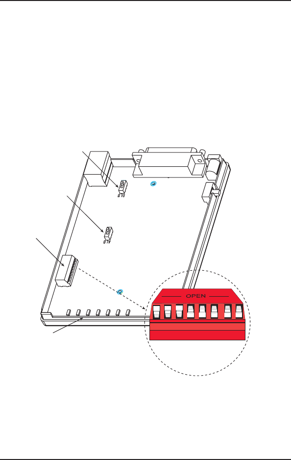
Controls on PC Board
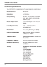
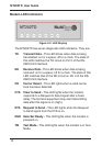
The MT202TD circuitry is on a single printed circuit (PC) board.
This board contains one 8-position DIP switch (numbered 1-8),
an analog loopback test switch, and a digital loopback test
switch. The factory default setting is for 4-wire, full-duplex
operation in normal mode. If you are using the modem in a 2-
wire configuration or using one of the test modes, you must
change the switch positions. Refer to page 19 for switch
setting and function information.
DIP-Switches
(1-8)
Analog Loopback
Switch (ALB)
Digital Loopback
Switch (DLB)
LED Indicators
Default Switch
Positions
1
2
3
45
6
78
Figure 2–3. PC Board Controls