


Chapter 2 - Installation & Connection
15
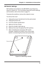
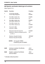
DIP Switch Settings
DIP switches are located on the MT202TD circuit board as
shown in Figure 2-3. For information about DIP switch settings
and functions, refer to the chart on page 19.
To access the switches, remove the modem’s cover.
To remove the cover:
1. Unplug the power transformer from the wall socket.
2. Unplug the phone line.
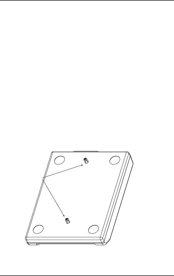
3. Turn the modem upside down.
4. Remove the two screws.
5. Place the modem right side up.
6. Remove the cover to expose the DIP switches.
7. After completing the necessary DIP switch
changes, replace the modem cover and screws
before re-connecting the phone and power lines.
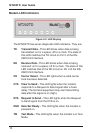
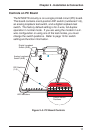
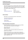
Remove Screws
Figure 2-5. Removing Screws