


12
Chapter 2 - Installation
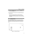
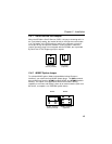
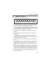
The sixteen DIP-Switches and two berg jumpers control various modem
options or set default values for the MT2834 Command mode. There is a
difference in how several of the switches operate depending on whether
you are in synchronous or asynchronous mode (DIP-Switch #12).
Most communications software packages have installation procedures of
their own, which call for certain modem DIP-Switch settings. If you are
using a package other than MultiExpress, follow the software's instructions.
2.3.1 DIP-Switch Settings
The vast majority of installations are similar, with the MT2834 being used
to dial up a remote installation where the call is automatically answered.
The factory default DIP-Switch settings are based on this assumption. The
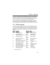
following is a brief description and summary of the MT2834's DIP-Switch
options:
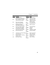
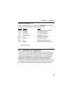
Switch Function Position Effect
#1 DTR Forced/ UP* DTR forced from
DTR from Interface * DOWN computer/terminal
#2 Flow Control &E4* UP* Hardware flow
(Async/Dial-Up/Leased Line) DOWN control enabled
#2 SDLC*/BSC (Sync) UP* SDLC enabled
DOWN
#3 Result Codes Enabled* UP Modem responses
(Async Dial-up) DOWN* are echoed
#3 DbM Transmit -15dB/-11dB* UP Lease Line
(Async/Sync/Leased Line) DOWN* transmits at -11dB
#4 UUCP Disabled* (Async UP* UUCP
Dial-Up/Leased Line) DOWN "spoofing" Disabled
#4 AS/400 Mode Disabled* UP* AS/400 Mode
(Sync Dial-Up/Leased Line) DOWN Disabled
#5 Auto-Answer Enabled* UP* Auto-Answer
Async/Sync/Dial-Up) DOWN in dial-up mode
* Factory default setting.