


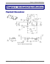

Chapter 3 – Electrical Characteristics
Multi-Tech Systems, Inc. SocketModem MT5600SMI Developer’s Guide 16
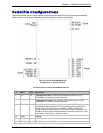
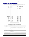
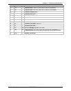
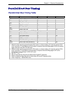
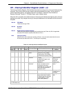
Parallel Host Bus Timing
Parallel Host Bus Timing Table
Symbol Parameter Min Max Units
READ (See Notes)
t
AS
Address Setup 5 - ns
t
AH
Address Hold 10 - ns
t
CS
Chip Select Setup 0 - ns
t
CH
Chip Select Hold 10 - ns
t
RD
RD Strobe Width 45 - ns
t
DD
Read Data Delay - 25 ns
t
DRH
Read Data Hold 5 - ns
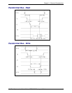
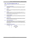
WRITE (See Notes)
t
AS
Address Setup 5 - ns
t
AH
Address Hold 15 - ns
t
CS
Chip Select Setup 0 - ns
t
CH
Chip Select Hold 10 - ns
t
WT
WT Strobe Width 75 - ns
t
DS
Write Data Setup (see Note 4) - 20 ns
t
DWH
Write Data Hold (see Note 5) 5 - ns
Notes:
1. When the host executes consecutive Rx FIFO reads, a minimum delay of 2 times the internal CPU
clock cycle plus 15 ns (85.86 ns at 28.224 MHz) is required from the falling edge of RD to the falling
edge of the next Host Rx FIFO RD clock.
2. When the host executes consecutive Tx FIFO writes, a minimum delay of 2 times the internal CPU
clock cycle plus 15 ns (85.86 ns at 28.224 MHz) is required from the falling edge of WT to the
falling edge of the next Host Tx FIFO WT clock.
3.
t
RD'
t
WT
=
t
CYC
+ 15 ns.
4.
t
DS is measured from the point at which both CS and WT are active.
5
.
t
DWH is measured from the point at which either CS and WT become active.
6. Clock Frequency = 28.224 MHz clock.