Chapter 5 – AT Commands, S-Registers, and Result Codes
Multi-Tech Systems, Inc. SocketModem MT5600SMI Developer’s Guide 78
Register Unit Range Default Description
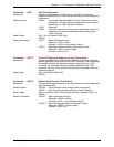
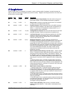
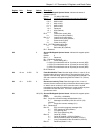
S27 73 (49Ah) General Bit-Mapped Options Status: Indicates the status of
command options.
Default: 73 (49h) (01001001b)
Bits 0, 1, 3 Synchronous/asynchronous selection (&Mn/&Qn)
310
0 0 0 &M0 or &Q0
001 &M1 or &Q1
010 &M2 or &Q2
011 &M3 or &Q3
1 0 0 Reserved
1 0 1 &Q5 (Default.)
110 &Q6
Bit 2 Leased line control (&Ln)
0 = Dial up line (&L0) (Default.)
Bits 4 - 5 Internal clock select (&Xn)
0 = Internal clock (&X0) (Default.)
1 = External clock (&X1)
2 = Slave clock (&X2)
Bit 6 CCITT/Bell mode select (Bn)
0 = CCITT mode (B0)
1 = Bell mode (B1) (Default.)
Bit 7 - Reserved
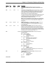
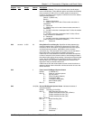
S28 0 General Bit-Mapped Options Status: Indicates bit mapped options
status.
Default: 0
Bits 0 - 1 Reserved
Bit 2 Reserved (always 0).
Bits 3 - 4 Pulse dialing (&Pn)
0 = 39%-61% make/break ratio at 10 pulses per second (&P0)
1 = 33%-67% make/break ratio at 10 pulses per second (&P1)
2 = 39%-61% make/break ratio at 20 pulses per second (&P2)
3 = 33%-67% make/break ratio at 20 pulses per second (&P3)
Bit 5-7Reserved
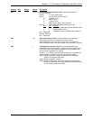
S29 10 ms 0–255 70 Flash Dial Modifier Timer: Sets the length of time, in units of 10 ms,
that the modem will go on-hook when it encounters the flash (!) dial
modifier in the dial string. S29 is a country dependent parameter. The
S29 value cannot be changed using S29=XX. Default: 70 (700 ms)
for U.S.
S30 10 s 0–255 0 Disconnect Inactivity Timer: Sets the length of time, in tens of
seconds, that the modem will stay online before disconnecting when
no data is sent or received. In error-correction mode, any data
transmitted or received will reset the timer. In other modes, any data
transmitted will reset the timer. The timer is inoperative in
synchronous mode.
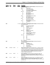
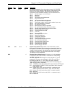
S31 192 (C0h) General Bit-Mapped Options Status: Indicates bit mapped options
status.
Default: 192 (C0h) (11000000b)
Bit 0 Single line connect message enable/disable (\Vn)
0 = Messages controlled by S95, Wn and Vn (\V0)
(Default.)
1 = Single line connect message (\V1)
Bit 1 Reserved (0)
Bits 2-3 Error correction progress messages (Wn)
0 = DTE speed only (W0) (Default.)
1 = Full reporting (W1)
2 = DCE (line) speed only (W2)
Bits 4-5 Caller ID (+VCID)
0 = Caller ID disabled (+VCID=0) (Default.)
1 = Short (formatted) Caller ID enabled (+VCID=1)
2 = Long (unformatted) Caller ID enabled (+VCID=2)
Bits 6-7 Reserved (Default = 11b)


