


Chapter 4 – SocketModem Parallel Interface – A Programmer's Description
Multi-Tech Systems, Inc. SocketModem MT5600SMI Developer’s Guide 23
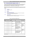
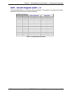
LCR – Line Control Register (Addr = 3)
The Line Control Register (LCR) specifies the format of the asynchronous data communications
exchange.
Bit 7 Divisor Latch Access Bit (DLAB)
This bit must be set to a 1 to access the Divisor Latch Registers during a read or write operation.
It must be reset to a 0 to access the Receiver Buffer, the Transmitter Buffer, or the Interrupt
Enable Register.
Bit 6 Set Break
When bit 6 is a 1, the Transmit data is forced to the break condition, i.e., space (0) is sent. When
bit 6 is a 0, break is not sent. The Set Break bit acts only on the Transmit data and has no effect
on the serial in logic.
Bit 5 Stick Parity
When Parity is enabled (LCR3 = 1) and stick parity is selected (LCR5 = 1), the parity bit is
transmitted and checked by the receiver as a 0 if even parity is selected (LCR4 – 1) or a 1 if odd
parity is selected (LCR4 = 0). When the stick parity is not selected (LCR3 = 0), parity is transmit
and checked as determined by the LCR3 and LCR4 bits.
Bit 4 Even Parity Select (EPS)
When parity is enabled (LCR3 = 1) and stick parity is not selected (LCR5 = 0), the number of 1s
transmitted or checked by the receiver in the data word bits and parity bit is either even (LCR4 =
1) or odd (LCR4 = 0).
Bit 3 Enable Parity (PEN)
When bit 3 is a 1, a parity bit is generated in the serial out (transmit) data stream and checked in
the serial in (receive) data stream as determined by the LCR4 and LCR5 bits. The parity bit is
located between the last data bit and the first stop bit.
Bit 2 Number of Stop GBITS (STB)
This bit specifies the number of stop bits in each serial out character. If bit 2 is a 0, one stop bit is
generated regardless of word length. If bit 2 is a 1 and 5-bit word length is selected, one and
one-half stop bits are generated. If bit 2 is a 1 and 6-, 7-, or 8-bit word length is selected, two
stop bits are generated. The serial in logic checks the first stop bit only, regardless of the number
of stop bits selected.
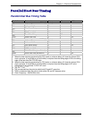
Bit 1-0 Word Length Select (WLS0 and WLS1)
These two bits specify the number of bits in each serial in or serial out character. The encoding
of bits 0 and 1 is:
Bit 1 Bit 0 Word Length
0 0 5 Bits (Not supported)
0 1 6 Bits (Not supported)
10 7 Bits
11 8 Bits