


Table of Contents
Multi-Tech Systems, Inc. SocketModem MT5600SMI Developer’s Guide 3
Contents
Chapter 1 – Product Description and Specifications................................................................................ 5
Introduction ................................................................................................................................................ 5
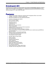
Product Description ................................................................................................................................... 5
Features..................................................................................................................................................... 6
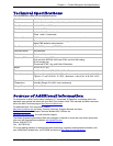
Technical Specifications............................................................................................................................ 7
Sources of Additional Information.............................................................................................................. 7
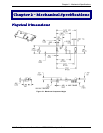
Chapter 2 – Mechanical Specifications ...................................................................................................... 8
Physical Dimensions ................................................................................................................................. 8
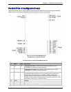
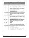
Serial Pin Configurations........................................................................................................................... 9
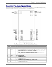
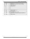
Parallel Pin Configurations ...................................................................................................................... 11
Chapter 3 – Electrical Characteristics...................................................................................................... 13
Handling Precautions .............................................................................................................................. 13
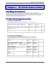
I/O Electrical Characteristics ................................................................................................................... 13
3.3V Serial SocketModem ...................................................................................................................13
3.3V Parallel SocketModem.................................................................................................................13
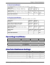
5V Serial SocketModem ......................................................................................................................14
5V Parallel SocketModem....................................................................................................................14
Operating Conditions............................................................................................................................... 14
Absolute Maximum Ratings..................................................................................................................... 14
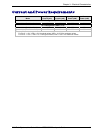
Current and Power Requirements........................................................................................................... 15
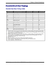
Parallel Host Bus Timing ......................................................................................................................... 16
Parallel Host Bus Timing Table ...........................................................................................................16
Parallel Host Bus - Read......................................................................................................................17
Parallel Host Bus - Write......................................................................................................................17
Chapter 4 – SocketModem Parallel Interface – A Programmer’s Description...................................... 18
SocketModem Parallel Interface.............................................................................................................. 18
Overview.................................................................................................................................................. 18
Register Signal Definitions ...................................................................................................................... 20
IER – Interrupt Enable Register (Addr = 1, DLAB = 0)........................................................................20
FCR – FIFO Control Register (Addr = 2, Write Only) ..........................................................................21
IIR – Interrupt Identifier Register (Addr = 2) ........................................................................................22
LCR – Line Control Register (Addr = 3)...............................................................................................23
MCR – Modem Control Register (Addr = 4) ........................................................................................24
LSR – Line Status Register (Addr = 5) ................................................................................................25
MSR – Modem Status Register (Addr = 6) ..........................................................................................26
RBX – RX Buffer (Receiver Buffer Register) (Addr = 0, DLAB = 0) ....................................................26
THR – TX Buffer (Transmitter Holding Register) (Addr = 0, DLAB = 0) ..............................................26
SCR – Scratch Register (Addr = 7)......................................................................................................27
Receiver FIFO Interrupt Operation.......................................................................................................... 28
Receiver Data Available Interrupt........................................................................................................28
Receiver Character Timeout Interrupts................................................................................................28
Transmitter FIFO Interrupt Operation...................................................................................................... 28
Transmitter Empty Interrupt .................................................................................................................28
Chapter 5 – AT Commands, S-Registers, and Result Codes................................................................. 29
Introduction.............................................................................................................................................. 29
Data Commands...................................................................................................................................... 30
Generic Modem Control Commands ...................................................................................................30
DTE-Modem Interface Commands......................................................................................................36
Call Control Commands.......................................................................................................................41
Modulation Control Commands ...........................................................................................................51
Error Control Commands.....................................................................................................................55
Data Compression Commands............................................................................................................60
V.8/V.8bis Commands .........................................................................................................................63
Diagnostic Commands.........................................................................................................................65