


Chapter 10 − Modem Mode AT Commands, S-Registers, and Result Codes
Multi-Tech Systems, Inc. MultiConnect Serial-to-Serial Adapter User Guide (S000354A) 109
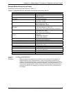
Command: #UD Last Call Status Report (Not available in V.22bis)
Description: #UD is an action command requesting logged operation events reporting. It does not take
parameters and must be the last command in the command line.
The modem logs aspects of their operation for each call, and saves these results until
cleared by one of the following events:
Power off.
Hard reset (e.g., negate DTR with &D3 set; reset button).
Soft reset = ATZ or AT&F.
ATD command issued.
ATA command issued.
Automatic answer (e.g., set register S0>0 and ring detected).
These results are NOT cleared by changing DTR, V.24 circuit 108.2, if &D0, &D1 or &D2.
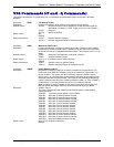
Data Call State Model:
For purposes of this command, there are four data call states, and associated status issues:
1. Call Setup
-Calling DCE: get dial tone, generate dial digits, and detect call progress signals.
-Answering DCE: detect ringing, detect Caller ID, etc.
2. Negotiation
-V.25 calling tone/answer tone exchanges
-V.8 or V.8bis call function negotiations
-V-series modem carrier detection and training
-Modem-to-modem protocols (e.g., V.42, V.42bis).
3. Data Transfer
-Bit-error rates, for each direction
-Rate renegotiation
-Retraining
4. Call Termination
-protocol disconnect signals
-carrier disconnect signals
-loss of carrier
-excessive error rates
Command Syntax:
In response to this command, the modem will report one or more lines of information text as
defined below. Information text format conforms to V.250; each line is preceded by a
<CR><LF> pair, and terminated by <CR><LF>. (CR and LF characters may be changed by
writing new values to the contents of registers S3 and S4, respectively.)
The modem may generate a single line or multiple lines, followed by
OK result code. For
example, if call setup failed, only that result is useful. Each information text line is formatted
as follows, including one or more key=value pairs:
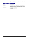
Response: DIAG <token key=value [[key=value] [key=value]] …>
Defined Values: DIAG 5 hexadecimal characters (44h, 49h, 41h, 47h, 20h)
< Left angle bracket (less than sign) (3Ch) token Unique 32-bit hexadecimal
string 2A4D3263(32h, 4h1, 34h, 44h, 33h, 32h, 36h, 33h)
space space character (20h)
Key One- or two-digit hexadecimal number (see Key in Table 8-2)
= Equal sign (3Dh)
Value Any string as defined below (Table 8-2 - Table 8-7 as appropriate)
> Right angle bracket (greater than sign) (3Eh)
Unless otherwise noted, all values are hexadecimal numbers. Any numeric values from
tables in ITU V.58 are converted to hexadecimal. Multi-digit values are reported MSD first.
Leading 0’s may be deleted. See examples in Table 4-13.
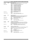
Monitoring an Active Connection
This command is intended for use after call termination. However, codes are defined so that
a modem can respond before the first call is placed, and during a call for live monitoring
purposes. For example, key 60, call termination, has value 1 defined, indicating that the call
is still in progress.
There are at least two ways to do this. First, the DTE could switch the modem to online
command state, issue the command, capture the responses, and then issue an ATO
command. For smoother online monitoring, in-band means defined in ITU V.80 are
recommended if available in the modem. If V.80 methods are used, each response line shall
be a separate extended in-band message.