


Chapter 10 − Modem Mode AT Commands, S-Registers, and Result Codes
Multi-Tech Systems, Inc. MultiConnect Serial-to-Serial Adapter User Guide (S000354A) 120
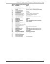
Register Unit Range Default Description
S14 138 (8Ah) General Bit-Mapped Options Status. Indicates the status of
command options.
Bit 0 This bit is ignored.
Bit 1 Command echo (En)
0 = Disabled (E0)
1 = Enabled (E1) (Default.)
Bit 2 Quiet mode (Qn)
0 = Send result codes (Q0) (Default.)
1 = Do not send result codes (Q1)
Bit 3 Result codes (Vn)
0 = Numeric (V0)
1 = Verbose (V1) (Default.)
Bit 4 Reserved
Bit 5 Tone (T)/Pulse (P)
0 = Tone (T) (Default.)
1 = Pulse (P)
Bit 6 Reserved
Bit 7 Originate/Answer
0 = Answer
1 = Originate (Default.)
S16 0 Test Mode Bit-Mapped Options Status. Indicates the test in
progress status.
Bit 0 Local analog loopback
0 = Disabled (Default.)
1 = Enabled (&T1)
Bits 1-7 Not used
S19 and S20 Reserved
S21 52 (34h) V.24/General Bit-Mapped Options Status. Indicates the status of
command options.
Bits 0 - 1 Reserved (0)
Bit 2 CTS behavior (&Rn)
0 = CTS tracks RTS (&R0)
1 = CTS always on (&R1) (Default.)
Bits 3-4 DTR behavior (&Dn)
0 = &D0 selected
1 = &D1 selected
2 = &D2 selected (Default.)
3 = &D3 selected
Bit 5 RLSD (DCD) behavior (&Cn)
0 = &C0 selected
1 = &C1 selected (Default.)
Bit 6 DSR behavior (&Sn)
0 = &S0 selected (Default.)
1 = &S1 selected
Bit 7 Long space disconnect (Yn)
0 = Y0 (Default.)
1 = Y1