


Chapter 10 − Modem Mode AT Commands, S-Registers, and Result Codes
Multi-Tech Systems, Inc. MultiConnect Serial-to-Serial Adapter User Guide (S000354A) 95
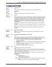
Command:
&V1 Display Last Connection Statistics (&V1 has no functionality in V.22bis)
Values: n = 1
Default: 1
Description:
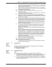
Displays the last connections in the following format (shown with typical results):
TERMINATION REASON.......... LOCAL REQUEST
LAST TX rate................ 26400 BPS
HIGHEST TX rate............. 26400 BPS
LAST RX rate................ 49333 BPS
HIGHEST RX rate………… 49333
BPS PROTOCOL………….. LAPM
PROTOCOL………………… LAPM
COMPRESSION................. V42Bis
Line QUALITY................ 038
Rx LEVEL.................... 015
Highest Rx State............ 67
Highest TX State............ 67
EQM Sum..................... 00B4
Min Distance................ 0000
RBS Pattern................. 00
Rate Drop................... 00
Digital Loss................ 2000
Local Rtrn Count............ 00
Remote Rtrn Count........... 00
Flex 9481814347C4
RBS Pattern: Shows which bits are being robbed in the least significant 6 bytes, e.g., 03
indicates 2 robbed bits in bit positions 0 and 1.
Digital Loss: Shows if a pad is encountered and if so, what is the digital loss. 2000 means 0dB.
Flex: Shows V.8bis information as follows:
First byte: Octet 13 (second byte of manufacturer id, 94 = K56flex)
Second byte: Octet 14 (Licensee code: 81 = Conexant)
Third byte: Octet 15 (manufacturer's product capabilities)
Fourth byte: Octet 16 (K56flex version number)
Fifth byte: Octet 17 (Conexant pump code version number)
Sixth byte: Octet 18 (x-law and controller version number)
Bit 6 Forced/Not forced A-Law/
µ-Law
0 = Forced A-Law/
µ-Law
1 = Not forced A-Law/
µ-Law
Bit 5 Select A-Law or
µ-Law
0 = Select A-Law
1 = Select
µ-Law
Bit 4:0 Controller version
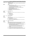
Command:
&Wn Store Current Configuration Settings (Not available in V.22bis)
Values: n = 0, 1
Default: 0
Description:
Saves the current (active) configuration (profile), including S-Parameters, in one of the two
user profiles in NVRAM as denoted by the parameter value. The current configuration is
comprised of a list of storable parameters illustrated in the
&V command. These settings are
restored to the active configuration upon receiving a
Z command or at power up (see &Y
command).
&W0 Store the current configuration as profile 0.
&W1 Store the current configuration as profile 1.
Command: &Y Designate a Default Reset Profile (No available in V.22bis)
Values: 0, 1
Default: None
Description:
This command selects which user profile will be used after a hard reset.
&Y0 The modem will use profile 0.
&Y1 The modem will use profile 1.