


4 - 1
IV. APPLICATION
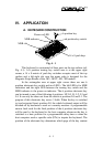
A. KEYBOARD CONSTRUCTION
MAGNETICMAGNETIC
STRIPESTRIPE
READERREADER
POWERPOWER
L4L4
L3L3
L2L2
L1L1
LOLO
LPLP
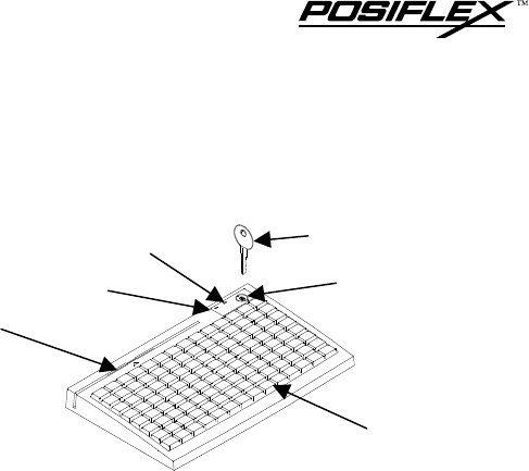
Fig. 4 - 1
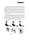
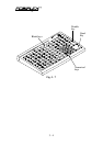
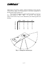
This keyboard is constructed of three parts on the top surface (ref.
Fig. 4-1). A 6 position turning key switch area is at the upper right
corner, a 14 x 8 matrix of push key switches occupies most of the top
surface and a left-right slot near the upper edge is designed for the
Magnetic Stripe Reader of the -M2, -M2/3, -M3, -MJ models.
In the rectangular area at upper right corner there are one 6
position electronic key switch and two LED’s. The left LED is for MSR
indication and the right LED between the turning key switch and the
MSR indicator is the power-on indicator. The 6 position electronic key
can be turned to one of the following 6 positions: LP, L0, L1, L2, L3 and
L4. It can only be taken out from the switch at positions L0 and L1. The
purpose of this electronic key serves 3 folds: When the key is switched
to (and extracted from) position L0, the whole keyboard output will be
blocked off by hardware to work as a security measure. A programmable
answer back code for the final position of the 6 position electronic key
will be sent by the keyboard to the host computer whenever the key is
switched to a new position for a programmable delay time or when the
host computer sends a specific code (E7h) to inquire the keyboard. The
position of the electronic key determines which page of the key content
MSR slot
MSR indicator
Power-on LED
6 position key
6 position key switch
14 x 8 push keys