Chapter 2 VirtualBench-Scope
Getting Started with VirtualBench 2-2
©
National Instruments Corporation
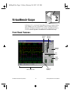
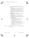
The front panel of VirtualBench-Scope has the following features:
• Channel Selector—selects a waveform for display on the Graphics
display.
• Channel Settings—adjusts the vertical sensitivity of the selected
channel. Turning the knob clockwise increases the sensitivity (each
vertical division represents a smaller voltage value).
• Timebase—allows you to change the timebase setting. Turning the
knob clockwise results in a shorter time period displayed in the
Graphics display (each horizontal division represents a shorter time
period).
• Graphics Display—displays waveforms.
• Vertical Slider—adjusts voltage offset for each channel. This slider
is useful when you want to view multiple waveforms in the
Graphics display.
• Trigger Settings Group—controls the conditions required for a
signal to be acquired; for example, whether to wait for a digital
trigger before acquiring data, or whether to acquire data in free-run
mode (no triggering).
• Main Control Bar Buttons
– Run—acquires data continuously. When clicked off, the
VirtualBench-Scope is placed in idle mode.
– Single—instructs VirtualBench-Scope to perform a
single-sweep acquisition.
– Auto Setup—starts configuration of the scope for the best
timebase, volts per division, and trigger setting for each
channel currently selected with the channel selector.
– Mode—sets the mode of the scope to either Volts versus Time
or X versus Y mode.
– X Scroll—scrolls along the X-axis or time axis.
Note: Please refer to the VirtualBench-Scope Online Help for additional help on
the front panel items.
06Chap02.fm Page 2 Friday, February 28, 1997 3:21 PM


