Chapter 4 Using Your Serial Hardware
PCMCIA Serial for Windows Me/9x 4-4 ni.com
The scratch register is located at offset 7 from the base address of the port.
For example, if COM2 were located at base address 0x3F8, and you wanted
to set the PCMCIA-485 board to two-wire mode with DTR
control, you
would write a 0x02 to I/O address 0x3FF. The PCMCIA-485 board would
immediately switch to the two-wire mode with DTR
control.
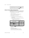
Setting the Transceiver Mode with DeviceIoControl
The NI-Serial software extends the
DeviceIoControl
Windows function
for programming the transceiver control mode. To program the transceiver
control mode using
DeviceIoControl
, complete the following steps:
1. Add the following lines to your source code:
#include <winioctl.h>
#define IOCTL_SERIAL_SET_TRANSCEIVER_MODE
CTL_CODE(FILE_DEVICE_SERIAL_PORT,37,
METHOD_BUFFERED,FILE_ANY_ACCESS)
2. Use the Win32 function
DeviceIoControl
, as follows:
a. Use the defined control code value listed in step 1 to set the
transceiver mode.
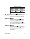
b. Use the input buffer values (unsigned long) listed in Table 4-3 for
programming different transceiver modes.
For example, to set TXRDY
two-wire auto control mode, use the
following code:
ULONG TranceiverMode = 131;
DeviceIoControl(hDevice,
IOCTL_SERIAL_SET_TRANSCEIVER_MODE,(PVOID)
&TransceiverMode,sizeof(ULONG),lpOutBuffer,
nOutBufferSize,lpBytesReturned,lpOverlapped);
Table 4-3.
DeviceIoControl Function Input Values
Transceiver Mode
DeviceIoControl
Function Input Value
Four-wire mode 128
Two-wire mode: DTR with echo 129
Two-wire mode: DTR controlled 130
Two-wire mode: TXRDY auto control 131


