


[c]FP-DO-403 4 ni.com
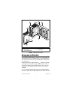
loads on the output channels, up to 2 A per channel.
1
Connect
the external power supply to multiple V and V
SUP
terminals and
to multiple C and COM terminals as needed to ensure that the
maximum current through any terminal is 2 A or less.
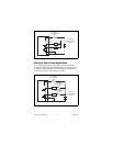
Install a 2 A maximum, fast-acting fuse (F2A 250V) between the
external power supply and the V
SUP
terminal on each channel.
Install a 2 A maximum, fast-acting fuse suitable for the load at the
V
OUT
terminal. Figure 3 shows fuses where appropriate.
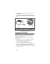
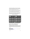
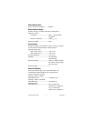
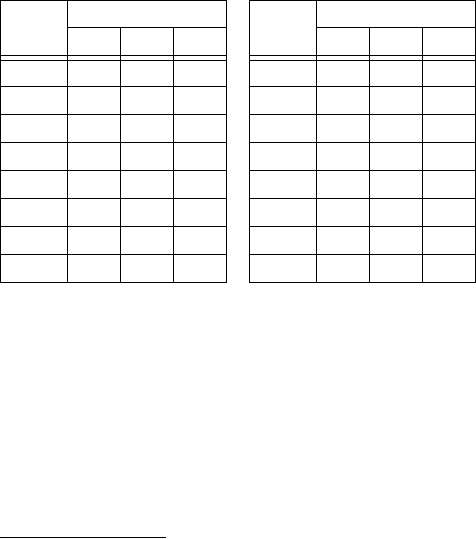
Table 1 lists the terminal assignments for the signals associated
with each channel. Terminal assignments and wiring diagrams are
also listed on the side panel of the cFP-DO-403 and under the
slide-in card on the front of the FP-DO-403 module.
National Instruments recommends that you wire the external
power supply to multiple V
SUP
and COM terminals. Figure 3
shows how to connect two output channels to loads.
Wiring for Low-Current Applications
If your application requires 2 A or less combined current through
all channels of the [c]FP-DO-403, you can wire your application
as shown in Figure 3. Install a 2 A maximum, fast-acting fuse
(F2A 250V) between the external power supply and the V terminal
as shown.
1
Refer to the Digital Output Circuit and Specifications sections for the maximum
output current level on all channels.
Table 1. Terminal Assignments
Channel
Terminal Numbers
Channel
Terminal Numbers
V
OUT
V
SUP
COM V
OUT
V
SUP
COM
0 1 17 18 8 9 25 26
1 2 17 18 9 10 25 26
2 3 19 20 10 11 27 28
3 4 19 20 11 12 27 28
4 5 21 22 12 13 29 30
5 6 21 22 13 14 29 30
6 7 23 24 14 15 31 32
7 8 23 24 15 16 31 32