


© National Instruments Corp. 7 [c]FP-DO-403
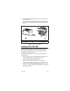
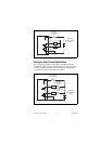
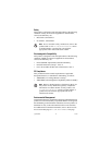
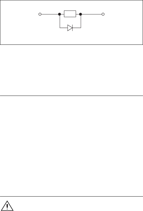
mount the flyback diode within 18 in. of the load. Figure 5 shows
a flyback diode connected to an inductive load.
Figure 5. Connection to Inductive Load with Flyback Diode
Although the [c]FP-DO-403 contains flyback diodes to prevent
excessively high voltage from damaging the module, National
Instruments recommends the use of an external protection circuit
across any inductive load.
Status Indicators
The [c]FP-DO-403 has two green status LEDs, POWER and
READY. After you insert the FP-DO-403 into a terminal base
or the cFP-DO-403 into a backplane and apply power to the
connected network module, the green POWER indicator lights
and the [c]FP-DO-403 informs the network module of its presence.
When the network module recognizes the [c]FP-DO-403, it sends
initial configuration information to the [c]FP-DO-403. After the
module receives this initial information, the green READY
indicator lights and the [c]FP-DO-403 is in normal operating
mode.
In addition to the green POWER and READY indicators, each
channel has a numbered, green output state indicator, which lights
when the channel is in the ON state.
Isolation and Safety Guidelines
Caution Read the following information before
attempting to connect the [c]FP-DO-403 to any circuits
that may contain hazardous voltages.
This section describes the isolation of the [c]FP-DO-403 and its
compliance with international safety standards. The field wiring
connections are isolated from the backplane and the inter-module
communication bus. The isolation barriers in the module provide
Flyback Diode
V
OUT
Load
V or V
SUP