


[c]FP-DO-403 6 ni.com
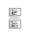
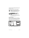
Digital Output Circuit
The [c]FP-DO-403 digital output channels are optically isolated
from the rest of the FieldPoint bank. In the ON state, a transistor is
turned on between the V
OUT
terminal and the external supply (the
C and COM terminals). In the OFF state, this transistor is turned
off, allowing only a small leakage current to flow. The V
OUT
terminal sinks current from external devices. Sinking current
means the V
OUT
terminal provides a path to the supply common.
Ensure that no channel sinks more than 2 A, and that the total
current supplied by all channels at any time is no more than 16 A
2
.
To determine whether the total current is within the limit, square
the current on each channel and add the squares together. If the sum
of all the squares is less than or equal to 16 A
2
, the total current is
within the limit. In the following example, three channels sink 2 A
and four channels sink 1 A each:
(2 A)
2
+ (2 A)
2
+ (2 A)
2
+ (1 A)
2
+ (1 A)
2
+ (1 A)
2
+ (1 A)
2
≤ 16 A
2
Caution The outputs must not be short-circuited to the
potential of the V or V
SUP
terminals (the positive voltage
of the external supply). Short circuits damage the
[c]FP-DO-403 output channels. Check all wiring
carefully before applying power.
In the ON state, there is an effective resistance of 0.12 Ω between
the output (V
OUT
) and the supply voltage (the C and COM
terminals). This resistance causes a voltage drop between the
external supply voltage and the output voltage. For example,
if the external supply voltage is 5 V and the output current is 1 A,
the output voltage is 4.88 V:
5 V – 1 A × 0.12 Ω = 4.88 V
Protection for Inductive Loads
When an inductive load, such as a motor or relay, is connected to
an output, a large counter-electromotive force may occur at
switching time because of the energy stored in the inductive load.
This flyback voltage can damage the outputs and the power supply.
It is best to limit such flyback voltages at the inductive load by
installing a flyback diode across the load. Typically, you should