


FP-RTD-122 and cFP-RTD-122 4 ni.com
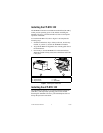
Wiring the [c]FP-RTD-122
The FP-TB-x terminal bases have connections for each of the eight
input channels on the FP-RTD-122. The cFP-CB-x connector
blocks provide the same connections for the cFP-RTD-122.
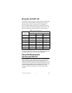
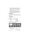
Table 1 lists the terminal assignments for the signals associated
with each channel. The terminal assignments are the same for the
FP-TB-x terminal bases and the cFP-CB-x connector blocks.
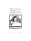
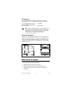
If you are using shielded wiring, you can reduce input signal noise
by connecting one end of the shield to the COM terminal. Do not
connect the shield to any of the wires at the signal end.
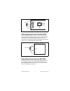
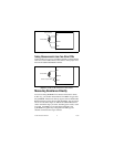
Taking RTD Measurements
with the [c]FP-RTD-122
The [c]FP-RTD-122 has eight input channels. All eight channels
share a common ground reference that is isolated from other
modules in the FieldPoint system. Each channel pulses a 0.25 mA
excitation current out of the EX+ terminal. The excitation current
returns through the COM terminal. The SENSE terminal measures
resistance and compensates for lead resistance errors. Each
channel is filtered, then sampled by a 16-bit analog-to-digital
converter.
Table 1. Terminal Assignments
Channel
Terminal Numbers
EX+ SENSE COM
0 1 2 18
1 3 4 20
2 5 6 22
3 7 8 24
4 9 10 26
5 11 12 28
6 13 14 30
7 15 16 32