


FP-RTD-122 and cFP-RTD-122 8 ni.com
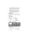
The [c]FP-RTD-122 uses a linearization curve known as the
Callendar-Van Dusen equation to measure the temperature of
RTDs. The equation is as follows:
Temperatures below 0 °C:
R
T
= R
0
[1 + A × T + B × T
2
+ C × T
3
× (T – 100 °C)]
Temperatures above 0 °C:
R
T
= R
0
[1 + A × T + B × T
2
]
T = temperature in °C
R
T
= RTD resistance at temperature T
R
0
= RTD nominal resistance at 0 °C
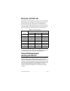
A, B, C are coefficients given in Table 2.
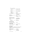
Table 2 lists the coefficients used in this equation for each of the
TCR values that the [c]FP-RTD-122 supports. If you have a
nonstandard RTD that does not match one of these linearization
curves, measure the resistance with the [c]FP-RTD-122 and
convert the resistance to temperature in the manner suggested by
the RTD vendor.
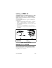
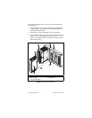
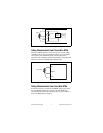
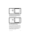
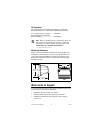
Three-Wire Compensation of Lead
Resistance Errors
The [c]FP-RTD-122 uses a three-wire compensation technique to
compensate for the lead resistances. The SENSE lead measures the
resistance of the return COM lead. If the EX+ lead has the same
resistance as the COM lead, the [c]FP-RTD-122 corrects for the
Table 2. Callendar-Van Dusen Coefficients Used by the [c]FP-RTD-122
TCR
mΩ/Ω/°C
A
(°C)
–1
B
(°C)
–2
C
(°C)
–4
3.750
a
3.81 × 10
–3
–6.02 × 10
–7
–6.0 × 10
–12
3.851
b
3.9083 × 10
–3
–5.775 × 10
–7
–4.183 × 10
–12
3.911
c
3.9692 × 10
–3
–5.8495 × 10
–7
–4.233 × 10
–12
3.916
d
3.9739 × 10
–3
–5.870 × 10
–7
–4.4 × 10
–12
3.920
e
3.9787 × 10
–3
–5.8686 × 10
–7
–4.167 × 10
–12
3.928
f
3.9888 × 10
–3
–5.915 × 10
–7
–3.85 × 10
–12