


© National Instruments Corp. 9 FP-RTD-122 and cFP-RTD-122
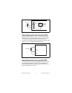
effects of the leads. The only residual errors are those caused by
mismatching the EX+ and COM leads. Most RTDs have lead
resistances within 5% of each other, so the compensation of the
[c]FP-RTD-122 corrects for 95% or more of the errors introduced
by lead resistances. This is a more accurate method than the typical
bridge completion methods described in many reference books.
The bridge methods not only have the same sensitivity to lead
resistance mismatch, but also are effective only for temperatures
very near those at which the bridge is balanced (usually 0 °C).
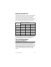
The temperature measurement accuracy specifications for the
[c]FP-RTD-122 at the end of these instructions include the effects
of a typical application using 10 m of 22 gauge copper wire
(approximately 0.5 Ω per lead), with 5% mismatch in the lead
resistances. If you are using leads with greater resistances, the
additional errors are approximately 3 °C per Ω of mismatch in the
lead resistances for 100 Ω RTDs, and 0.3 °C per Ω of mismatch in
the lead resistance for 1,000 Ω RTDs. For example, for 2 Ω leads
matched to 5% of each other, the lead resistance mismatch is
5% × 2 Ω = 0.1 Ω, which would cause 0.3 °C of error in
measurements of a 100 Ω RTD.
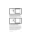
If you are using the [c]FP-RTD-122 with two-wire RTDs, the
errors due to lead resistances are much greater because three-wire
compensation is not used. With two-wire RTDs, the additional
errors are approximately 3 °C per Ω of the sum of the lead
resistances for 100 Ω RTDs, and 0.3 °C per Ω of the sum of lead
resistances for 1,000 Ω RTDs. For example, a 1,000 Ω two-wire
RTD with 2 Ω leads has a total lead resistance of 4 Ω (2 Ω per lead),
which causes 1.2 °C of error.
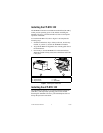
Status Indicators
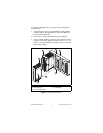
The [c]FP-RTD-122 has two green status LEDs, POWER and
READY. After you insert the [c]FP-RTD-122 into a terminal base
or backplane and apply power to the connected network module,
the green POWER indicator lights and the [c]FP-RTD-122
informs the network module of its presence. When the network
module recognizes the [c]FP-RTD-122, it sends initial
configuration information to the [c]FP-RTD-122. After the
[c]FP-AI-111 receives this initial information, the green READY
indicator lights and the module is in normal operating mode.