


Chapter 4 Theory of Operation
© National Instruments Corporation 4-5 DAQCard-700 User Manual
The A/D FIFO generates a signal that indicates when it contains A/D conversion data. The state
of this signal can be read from the Status Register.
The output from the ADC is a two's complement number ranging from -2,048 to 2,047. The
output from the 12-bit ADC is always sign-extended to 16 bits by the card circuitry so that data
values read from the FIFO are 16 bits wide.
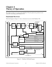
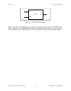
Data Acquisition Timing Circuitry
A data acquisition operation refers to the process of obtaining a series of successive A/D
conversions at a carefully timed interval. This interval is called the sample interval. The data
acquisition timing circuitry consists of various clocks and timing signals that perform this timing.
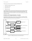
The DAQCard-700 can perform two types of data acquisition–single-channel data acquisition
and multichannel (scanned) data acquisition. Scanned data acquisition uses a counter to
automatically switch between analog input channels during data acquisition.
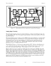
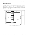
Data acquisition timing consists of signals that initiate a data acquisition operation and generate
scanning clocks. Sources for these signals are supplied mainly by timers on the DAQCard-700
card. One of the three counters of the onboard MSM82C54 is reserved for this purpose.
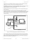
An A/D conversion can be initiated during data acquisition by a low-to-high transition on the
counter 0 output (OUT0) of the MSM82C54 onboard counter/timer chip on the DAQCard-700,
or by a low-to-high transition on EXTCONV* input.
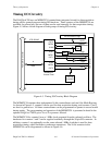
The sample-interval timer is a 16-bit down counter that uses the onboard 1 MHz clock to
generate sample intervals from 2 µs to 65,535 µs (see Timing I/O Circuitry later in this chapter).
Each time the sample-interval timer reaches zero, it generates a pulse and reloads with the
programmed sample-interval count. This operation continues until the counter is reprogrammed.
Notice that only counter 0 is required for data acquisition operations. The software must track
the number of conversions that have occurred and turn off counter 0 after the required number
has been obtained.
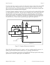
Single-Channel Data Acquisition
During single-channel data acquisition, a control register is set to select the analog input channel
before data acquisition is initiated. This multiplexer setting remains constant during the entire
data acquisition process; therefore, all A/D conversion data is read from a single channel.
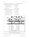
Multichannel (Scanned) Data Acquisition
Multichannel data acquisition is performed by enabling scanning during data acquisition.
Multichannel scanning is controlled by a scan counter.
For scanning operations, the scan counter decrements from the highest numbered channel
(selected by the user) through channel 0 and then repeats the sequence. For single-ended mode,
therefore, any number of channels from 2 to 16 can be scanned. For differential mode, any
number of channels from 2 to 8 can be scanned. Notice that the same analog input range is used
for all channels in the scan sequence.