


Index
© National Instruments Corporation Index-3 DAQCard-700 User Manual
I
input configurations, 3-5 to 3-7
DIFF
definition (table), 2-4
purpose, 2-4
differential mode, 3-6
instrumentation amplifier
illustration, 3-6
purpose, 3-6
recommended input configurations
(table), 3-7
RSE
definition (table), 2-4
purpose, 2-4
single-ended mode, 3-6
installation. See also configuration.
steps for installing DAQCard-700,
2-1 to 2-2
unpacking the DAQCard-700, 1-4
instrumentation amplifier
illustration, 3-6
purpose and use, 3-6
interrupt levels, C-2
I/O connector
exceeding maximum ratings
(warning), 3-1
pin assignments (illustration), 3-2
L
LabVIEW and LabWindows/CVI
application software, 1-2
M
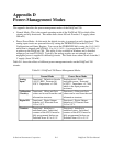
management, power modes, D-1
manual. See documentation
measurement systems
floating, 3-5
ground-referenced, 3-5
memory, C-2 to C-3
multichannel (scanned) data
acquisition, 4-5
N
NI-DAQ driver software, 1-3
O
operation of DAQCard-700. See also theory
of operation.
problems with, C-1
OUT, GATE, and CLK signals for general-
purpose timing, 3-14 to 3-17
OUT0 signal, 3-3
OUT1 signal, 3-3
OUT1* signal, 3-3
OUT2 signal, 3-3
P
PC-LPM-16, compared with
DAQCard-700, B-1
PCMCIA
I/O channel interface circuitry, 4-2 to 4-3
questions and answers, C-1 to C-3
physical specifications, A-2
power connections, 3-13
power-management modes, D-1
power requirement for DAQCard-700, A-2
programming. See software programming
choices for DAQCard-700.
pulse and square wave generation, 3-15
pulse-width measurement, 3-15
R
referenced single-ended input. See RSE
input.
register-level programming, 1-4
resources, C-2 to C-3
RSE input
configuration, 2-4
definition (table), 2-4
S
signal connections