


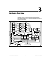
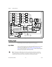

Chapter 3 Hardware Overview
NI 6115/6120 User Manual 3-4 ni.com
Considerations for Selecting Input Ranges
The range you select depends on the expected range of the incoming signal.
A large input range can accommodate a large signal variation but reduces
the voltage resolution. Choosing a smaller input range improves the voltage
resolution but may result in the input signal going out of range. For best
results, match the input range as closely as possible to the expected range
of the input signal.
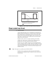
Input Coupling
You can configure the NI 6115/6120 for either AC or DC input coupling
on a per channel basis. Use AC coupling when the AC signal contains a
large DC component. If you enable AC coupling, you remove the large DC
offset for the input amplifier and amplify only the AC component. This
configuration effectively uses the dynamic range of the ADC.
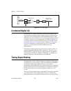
The input impedance for the programmable gain instrumentation amplifier
(PGIA) channels is 1 MΩ for ranges ≤ ±10 V and 10 kΩ for
ranges > ±10 V. This configuration provides an AC-coupled corner
frequency of 2.34 Hz for ranges ≤ ±10 V and 234 Hz for ranges > ±10 V.
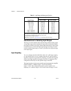
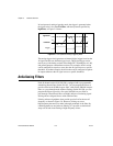
Table 3-1. Input Range and Measurement Precision
Input Range
Precision
1
6115 (12-Bit) 6120 (16-Bit)
–50 to +50 V
2
–20 to +20 V
–10 to +10 V
–5 to +5 V
–2 to +2 V
–1 to +1V
–500 to +500 mV
–200 to +200 mV
24.4 mV
9.77 mV
4.88 mV
2.44 mV
977 µV
488 µV
244 µV
97.7 µV
1.53 mV
610 µV
305 µV
153 µV
61.0 µV
30.5 µV
15.3 µV
6.10 µV
1
The value of 1 least significant bit (LSB) of the ADC; that is, the voltage increment
corresponding to a change of one count in the ADC count.
2
Do not exceed ±42 VDC maximum.
Note: Refer to Appendix A, Specifications, for absolute maximum ratings.