


Chapter 3 Hardware Overview
NI 6115/6120 User Manual 3-10 ni.com
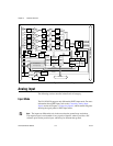
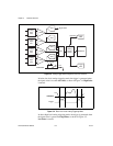
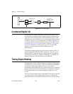
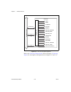
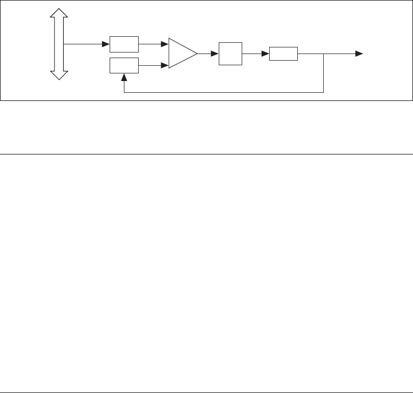
Figure 3-10. PLL Block Diagram
Correlated Digital I/O
The NI 6115/6120 contains eight lines of DIO for general-purpose use.
You can software-configure groups of individual lines for either input or
output. The NI 6115/6120 includes a FIFO for buffered operation. This
operation allows you to read/write an array of data, using either an internal
or external clock source, at a maximum rate of 10 MHz. In addition, you
can correlate DIO and AI/AO operations to the same clock. Refer to the
Correlating DIO Signal Connections section of Chapter 4, Connecting
Signals, for information on which signals you can use to clock DIO
operation. At system startup and reset, the DIO ports are all
high-impedance.
The hardware up/down control for general-purpose counters 0 and 1 are
connected onboard to DIO6 and DIO7, respectively. Thus, you can use
DIO6 and DIO7 to control the general-purpose counters. The up/down
control signals, GPCTR0_UP_DOWN and GPCTR1_UP_DOWN, are
input only and do not affect the operation of the DIO lines.
Timing Signal Routing
The DAQ-STC provides a flexible interface for connecting timing signals
to other devices or external circuitry. The NI 6115/6120 uses the RTSI bus
to interconnect timing signals between devices, and it uses the
programmable function input (PFI) pins on the I/O connector to connect the
device to external circuitry. These connections are designed to enable the
NI 6115/6120 to both control and be controlled by other devices and
circuits.
There are 13 timing signals internal to the DAQ-STC that can be controlled
by an external source. These timing signals can also be controlled by
signals generated by the DAQ-STC, and these selections are fully software
Phase Comp
Div/10
Div/60
VCXO
60 MHz out
synched to 10 MHZ
backplane clock
Loop
Filter
+
–
PXI Bus
10 MHz