


Chapter 3 I/O Information
NI PXIe-8105 User Manual 3-10 ni.com
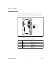
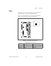
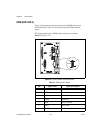
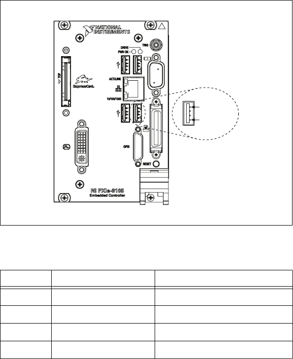
Universal Serial Bus
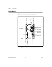
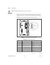
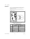
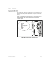
Figure 3-6 shows the location and pinouts for the Universal Serial Bus
(USB) connector on the NI PXIe-8105. Each controller has 4 USB ports on
the front panel. Table 3-7 lists and describes the USB connector signals.
Figure 3-6. USB Connector Location and Pinout
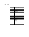
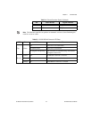
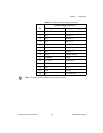
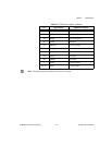
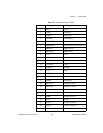
Table 3-7. USB Connector Signals
Pin Signal Name Signal Description
1 VCC Cable Power (+5 V)
2 –Data USB Data–
3 +Data USB Data+
4 GND Ground
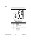
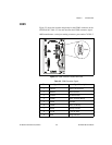
USB
4
1